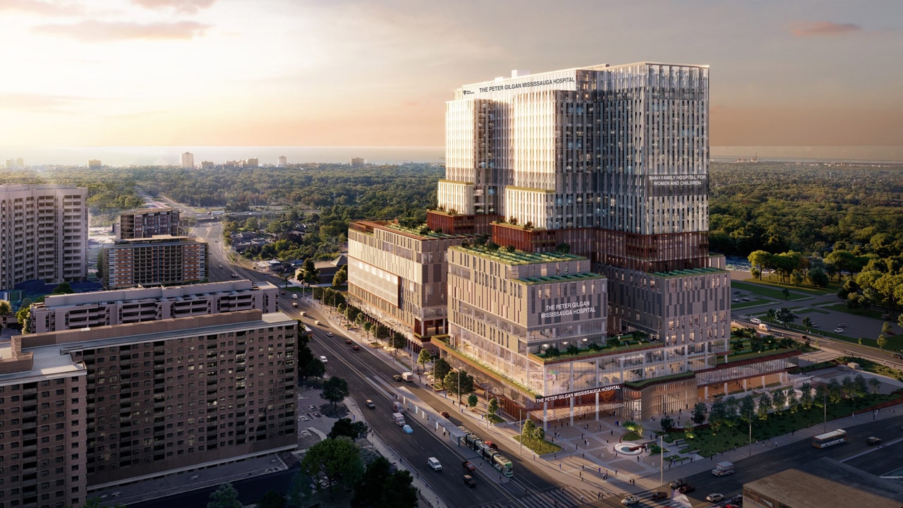
Peter Gilgan Mississauga Hospital · First DALI-2 system of this scale in North America
WaveLinxDALI-2
Designing an industry-first commissioning experience for a protocol-constrained commercial IoT product from zero to shipped, across hardware, firmware, and field reality simultaneously.
ENTERPRISE IOT
HEALTHCARE
INDUSTRY FIRST
FIRST RELEASE COMPLETE

ROLE
Lead Product Designer
COMPANY
Cooper Lighting Solutions (Signify)
PLATFORM
Mobile, Web
SCOPE
Research → Delivery
TEAM SIZE
15 Cross-functional
DESIGNED
2024-2026 - Figma
VISIT WEBSITE

Key Outcome ↑
Delivered a design solution that extended WaveLinx's commissioning and device management workflows to support DALI-2 at enterprise scale for one of the most complex hospital lighting deployments in North America. The non-blocking V2 architecture allowed contractors to configure areas while device import ran in parallel.
10,000+
Devices
24
Buses per Floor
6
DALI Hubs per Panel
3,072
Devices per Panel
128
Fixtures per Bus
1,000 ft
Max Bus Length
4,000 - 10,000
Devices per Hospital Floor
01
THE PROBLEM
What am I working with?
Cooper Lighting Solutions had built its commercial and healthcare lighting business on two legacy platforms, Fifth Light and iLight. Both were being discontinued. The WaveLinx DALI system was the designated replacement: a new, DALI-2-certified IoT platform extending WaveLinx Pro into large commercial buildings and hospitals. The first deployment: The Peter Gilgan Mississauga Hospital, the largest DALI-2 installation in North America.
There was no existing product to iterate on. This is a design inside a highly constrained hardware system. The DALI-2 protocol defines tight rules about how devices communicate on a bus, what operations must happen in sequence, and how long those operations take. The protocol cannot be changed. The UX had to work within it.
4,000+
Minimum devices on a typical hospitaldeployment, up to 10,000+ at full scale
40 Buses
Up to 20 DALI Hubs x 4 buses each per WAC Controller
128 Max
Devices per bus, 64 output control gear + 64 input control devices
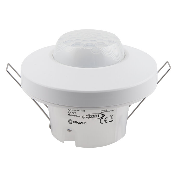
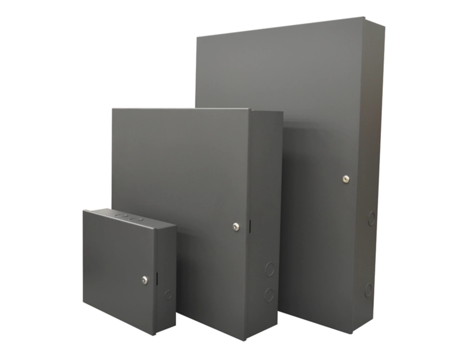
The Core UX Problem: Time
DALI's bus architecture has an inherent limitation: the protocol is slow. The V1 design model made it worse adding a Hub locked the UI with a blocking loader reading "Processing! This may take a while... Adding Dali Hub and Devices to WAC" that persisted until import completed. That import window started at 10 minutes. Engineering later increased it to 27.5 minutes per Hub to accommodate 250 physical DALI devices. Multiply that across 10 Hubs per WAC, and the scale of the blocking problem becomes concrete.
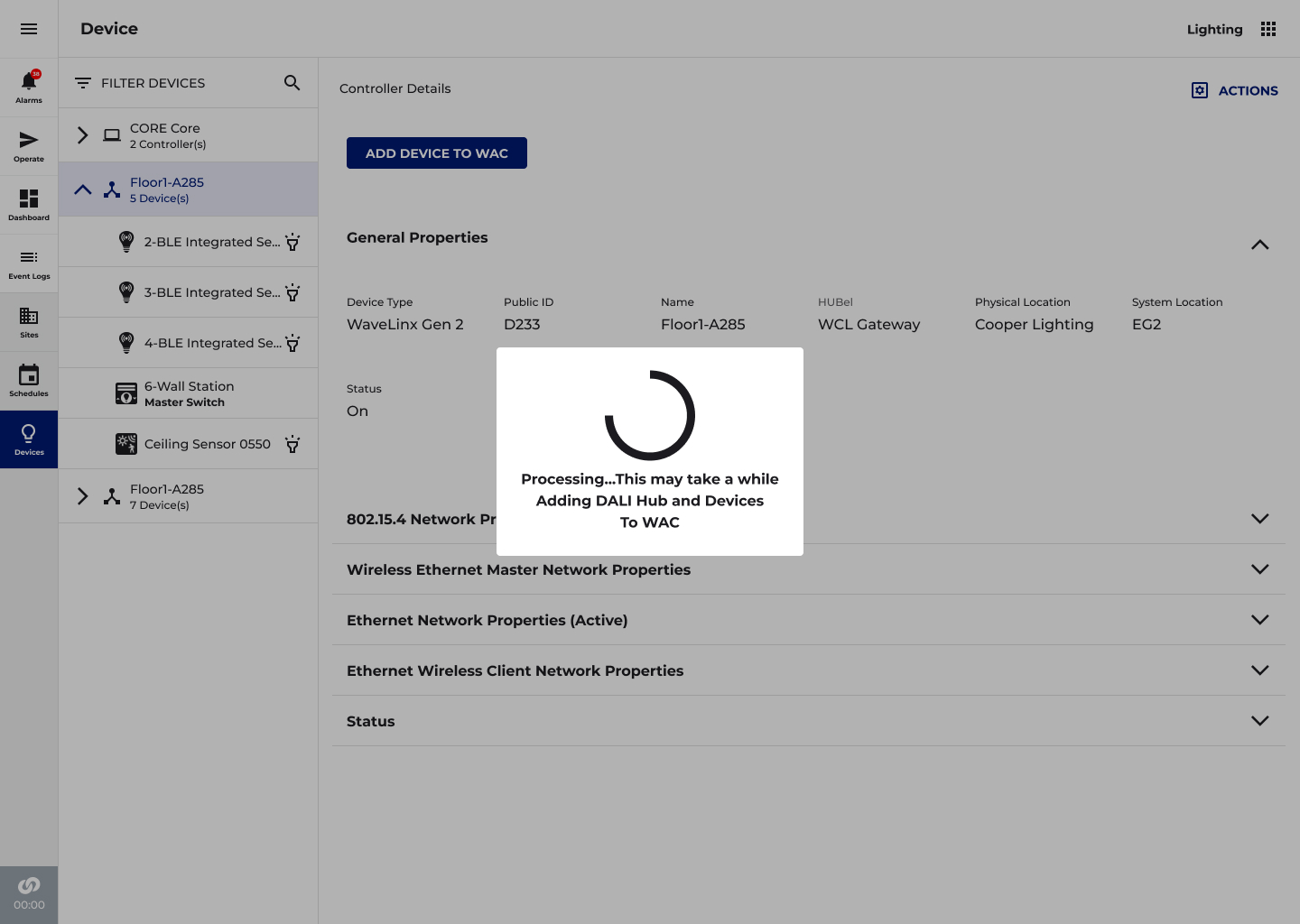
V1 Commissioning Problem
Discovery triggered an immediate full scan across all 4 buses. Adding a Hub locked the UI with a blocking loader, no navigation, no area creation, no configuration work possible until import completed. On large deployments this meant contractors sat idle during a protocol-imposed wait that could stretch past 10 minutes per Hub. No progress visibility, no fallback, no parallel work.
Business Stakes
This was the system replacing Fifth Light and iLight. Channel partners, integrators, and facilities teams at hospitals were evaluating whether WaveLinx DALI could credibly take over those workflows. Commissioning experience was a make-or-break differentiator, not a polish concern. A blocking experience at hospital scale was not acceptable.
02
MY ROLE AND SCOPE
Taking the Lead
I was the UX owner on DALI-2, the primary design story for the entire WaveLinx DALI commissioning system. I led UX strategy and design from discovery through handoff, collaborating cross-functionally with Engineering, Architecture, Product Management, Firmware, and Development. Milestone UX presentations were delivered to groups of 25+ stakeholders for feedback and alignment across the full initiative.
What I Owned
End-to-end commissioning UX across Hub Discovery, Lobby, Manage Hub, Area integration, and Floorplan view · V1 and V2 flow architecture · Custom iconography system (Adobe Illustrator → SVG/Fontello) · DALI-2 Hub hardware label design (press-ready) · Cross-functional design reviews · CLS Design System contributions in Figma · Launch followup
Direct team: Engineering Managers (2), ePO Engineering Product Owners (2), Product Managers (2), Architecture (1), Developers (5). I worked directly with the firmware engineer owning DALI bus scanning logic, translating protocol constraints into interaction affordances that felt coherent to end users.
Key Constraint
The DALI bus scan is slow by protocol design. Addressing 128 devices per bus and fetching device parameters takes real time. This was not a solvable engineering problem, the protocol ceiling is physical. The UX had to absorb the constraint and design around it, not through it.
03
SCOPING
Discovery, Research, Icons & System Design
Research and domain learning ran simultaneously with early design work, hardware prototypes and firmware builds were still in progress. My approach was to use the engineering team as a primary research source while the physical system was being built, supplemented by field context from channel partners and competitive teardown of existing DALI commissioning tools.
→
Deep protocol sessions with the firmware engineer, understanding what DALI-2 auto-addressing does, in sequence, and why it takes the time it takes
→
Review initiative documentation, mapping system architecture, device type hierarchy (DT6, DT8, Field Relay, CCI), and WAC capacity model
→
Legacy system teardown, evaluating Fifth Light and iLight commissioning to understand what behaviours installers expected to carry forward
→
Competitive analysis of 3 DALI commissioning platforms deployed in hospitals and commercial buildings
→
Early discovery workshops to surface bandwidth bottlenecks and technical constraints before any design work began stress-test audit of the full application, not just the DALI feature set
Research Approach
Discovery & Stakeholder AlignmentWith a project of this technical complexity, design-led research required bridging the gap between UX thinking and deep infrastructure knowledge. Work began with structured discovery sessions across five stakeholder groups before any design work started.
- Engineering & Firmware
Identified DALI bus bandwidth constraints, hub discovery latency, and the maximum polling frequency the system could support without degrading live commissioning
- Developers
Surfaced front-end rendering constraints, specifically, that loading 3,000+ devices into the existing device tree would time out and degrade the entire application
- Architecture & Product Management
Defined the hospital deployment context, commissioning workflow sequence, and regulatory requirements for wired-only environments
- Field Commissioning Teams
Described how technicians work on hospital floors: cross-referencing physical floor plans with MAC address lists, working bus-by-bus, and needing instant device identification under time pressure
- Hospital Facilities Teams
Articulated post-commissioning needs: adding devices during construction phase expansions, rebooting hubs without disrupting live floors, and identifying device faults quickly
User Input
I've been doing DALI for 12 years. I know what order things need to happen. But your app doesn't so I have to fight it.Master electrician, field context research participant
Key Research Insight
The single most important finding from discovery was that the existing WaveLinx architecture assumed a world of 30–50 devices per controller. Every piece of UI, device trees, area screens, the Operate floorplan, had been designed at that scale. DALI-2 didn’t just add a feature; it required re-examining how the entire application handled volume.
Custom Iconography System
The DALI 2-wire bus became the visual foundation of the icon system. The two-wire connection, the defining physical characteristic of every DALI device is embedded consistently across the icon set as a shared visual motif, allowing users to immediately recognize DALI devices as a category while differentiating by type at a glance. All icons were custom-designed in Adobe Illustrator, optimized for clarity at small sizes, exported in SVG format, and validated for rendering consistency via Fontello.

Fixture Dimmable

Light Fixture DT8

DT6 Single Channel

DT6 Dual Channel

Light Fixture CCT

DALI Hub

DALI Hub Bus

Dual Tech Sensor


PIR Sensor

Wall Station

Contact Closure Input

RSP DAC CCT

RSP DAC Dimmable

Relay on/off

Find Devices
DALI-2 Icon System — Custom designed in Adobe Illustrator
The two-wire bus motif is embedded in every device icon as a shared visual language, bridging physical installation and softwaremanagement. Exported as SVG, validated via Fontello for rendering consistency at all display sizes.
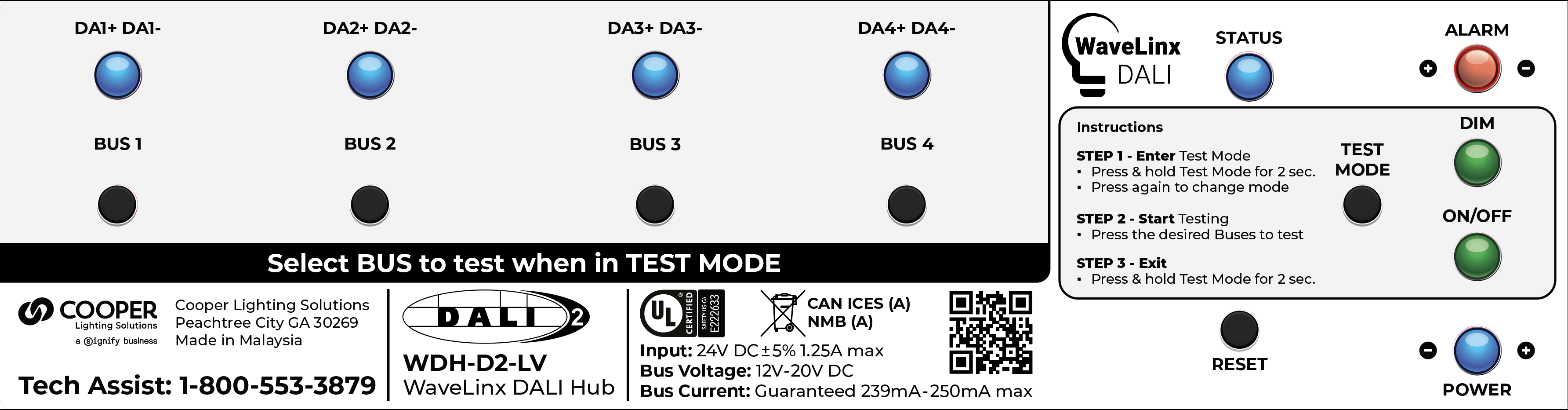
DALI-2 Label Design
A sticker will be added to the HUB hardware providing specifications, describing install/setup and technical assistance. Design was created in Adobe Illustrator and is press ready with die cut marks in PDF format.*Graphical place holders added for LED lights and button locations
Four Key Insights
Insight 1 — The wait time was a UX problem before it was a technical one
The DALI bus scan delay wasn't fixable at the firmware level for MVP. But V1 made it worse by blocking the entire UI. The opportunity wasn't to make scanning faster, it was to stop making the user wait for it. Design needed to decouple scan from configuration workflow entirely.
Insight 2 — Hub-first import was the right architecture
Early designs explored adding devices during Hub discovery. Research and engineering collaboration revealed this was wrong: the Hub is the unit of import; devices are a consequence. Hub-first simplified the mental model, reduced decisions at the most uncertain moment, and aligned with how MQTT pairing actually worked.
Insight 3 — DT8 (dual channel) drivers created an invisible complexity problem
DALI DT8 drivers (CCT, white) physically present as a single device but require two separate zone types, Dimmable and White Tunable. Users see one fixture on the wall, two objects in the app. This disconnect required specific UX abstraction to avoid commissioning errors.
Insight 4 — The device volume problem would break existing UI patterns
The existing Area screen was designed for manageable wireless device counts. A hospital floor running 6+ Hubs could surface thousands of fixtures, sensors, and wall stations simultaneously, flooding the screen and crippling load times. The entire navigation model needed reconsidering at scale.
Rapid Prototyping Process
Weekly cross-functional reviews were the primary feedback mechanism throughout the project. Each cycle followed the same structure
Week 1 - 2
Flows for each problem area shared with Engineering to validate technical feasibility
Week 3 - 4
Prototypes reviewed with Product Management and Architecture for workflow alignment
Week 5+
Flows reviewed weekly with full stakeholder group including Firmware and Development leads
This cadence compressed the feedback loop significantly and allowed design decisions to stay in lockstep with evolving engineering constraints, particularly as hub discovery latency numbers changed and affected what real-time feedback the UI could reliably provide.
04
PIVOT
The Version 1 → Version 2 Pivot
Midway through the project it became clear the V1 commissioning model was structurally broken for the wait time problem. The pivot from V1 to V2 was not a visual redesign, it was a fundamental change to the interaction architecture.
V1 Model — Abandoned
Discover Hubs AND Devices simultaneously. Adding a Hub blocks the UI with a loading screen, no navigation, no configuration possible. User waits through a 10-minute+ blocking import per Hub.
→
V2 Model — Shipped
Discover ONLY DALI Hubs. ADD TO WAC triggers Hub pairing AND background bus scan simultaneously. UI never blocks. Users immediately begin configuring Areas while device import runs in background.
The Reframe in One Sentence
We stopped designing for when scanning finishes and started designing for what users can do while its still running.
05
DESIGN
DALI Hub Discovery & Commissioning Flow
💡 DESIGNING FOR SPEED AND CONFIDENCE AT HOSPITAL SCALE
Commissioning a hospital-scale DALI-2 installation means a technician may be working through hundreds of hubs, buses, and thousands of devices, often cross-referencing physical floor plans with MAC addresses in real time. The discovery flow needed to be fast, forgiving, and transparent about what the system had found at every step.
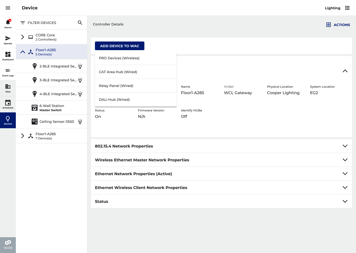
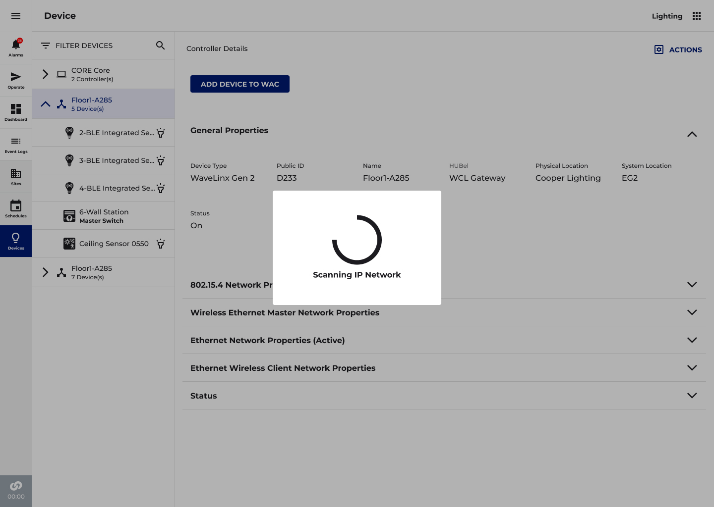
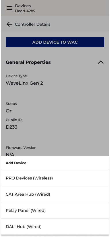
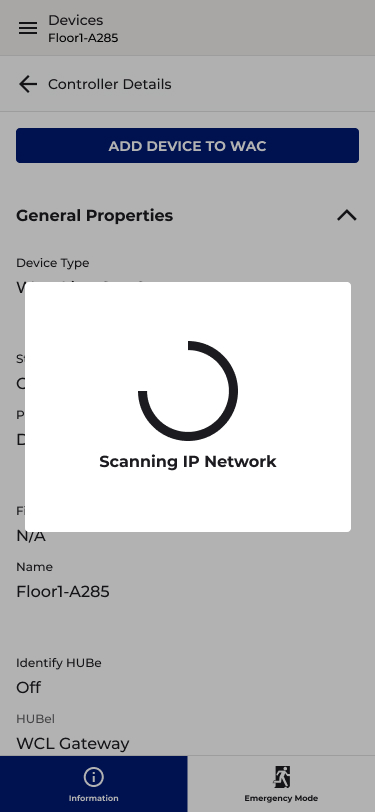
Step 1 — Scan the Network
From the Device screen, the technician initiates a network scan. A modal overlay confirms the system is actively scanning the IP network. Once complete, all discovered DALI Hubs are presented, each identified by name, MAC address, and IP address, ready to be imported into the WAC.
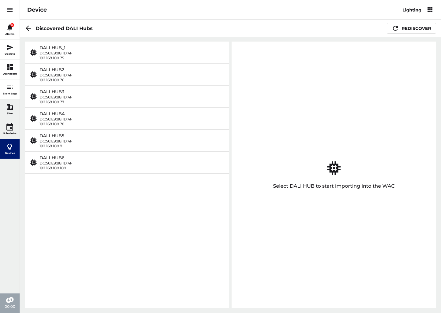
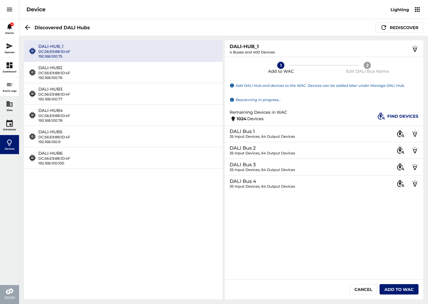
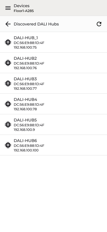
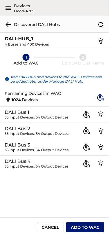
Step 2 — Select & Add a Hub
Selecting a Hub reveals a two-step stepper. All 4 buses shown with live device counts (Input and Output separately). Persistent Remaining Devices counter tracks across the full installation.
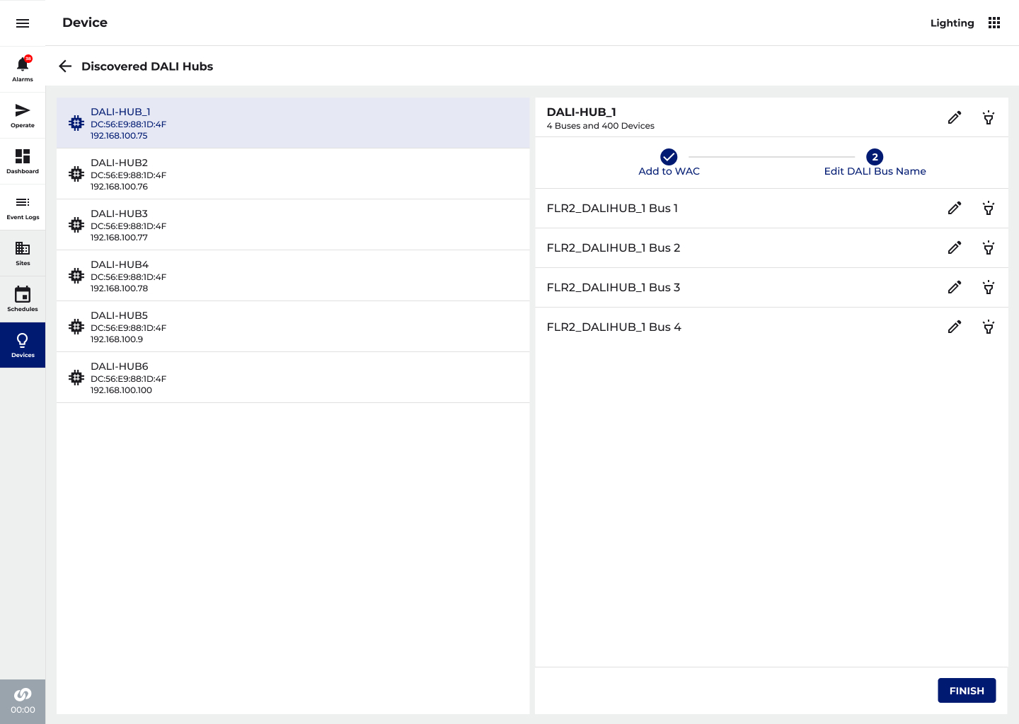
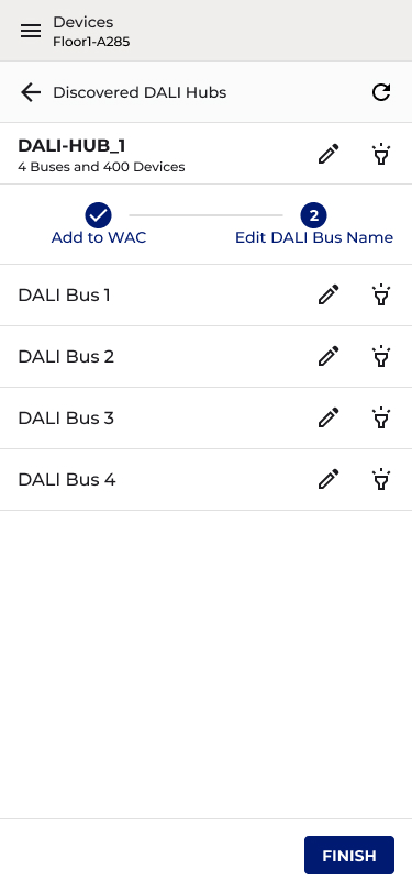
Step 3 — Name the Hub and Buses
Step 2 of the stepper prompts renaming using a consistent naming convention tied to floor and location. Inline edit and delete controls keep the interface clean. FINISH returns to the hub list.
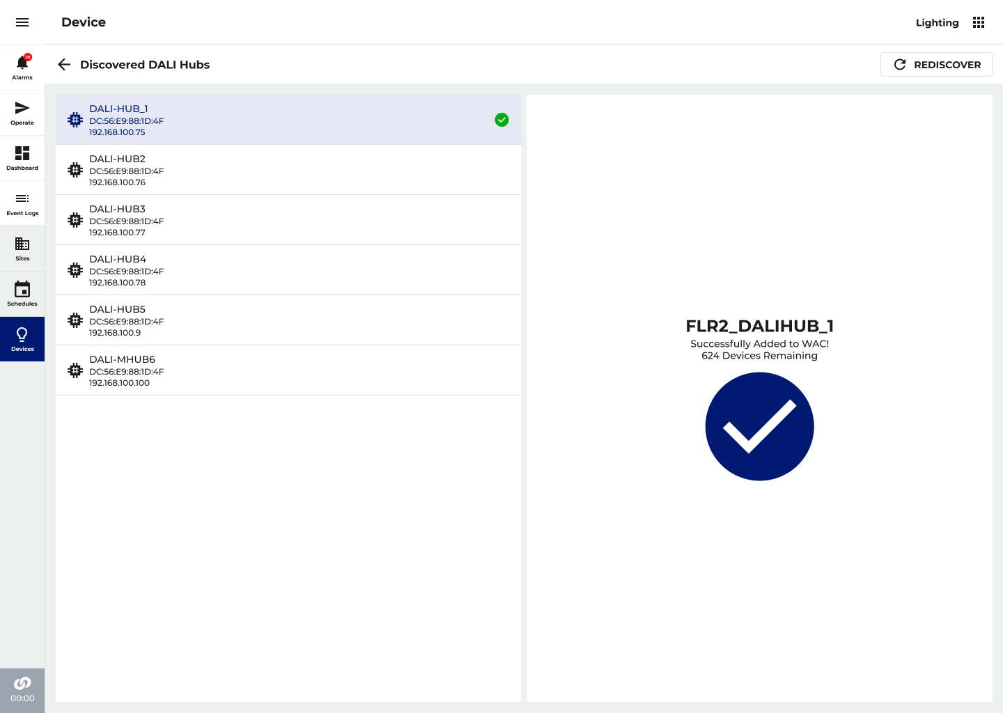
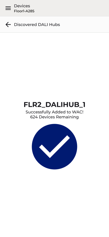
Success State
Import confirmed with hub name, checkmark, and remaining device count, so the technician can move confidently to the next hub. Green tick appears against the Hub name in the list, indicating WAC import is complete.
06
DESIGN
DALI Hub Management
💡 ONGOING DEVICE MANAGEMENT AT HOSPITAL SCALE
Initial commissioning is only the beginning. Hospitals expand, floors get reconfigured, and new devices get added to existing buses over time. The Manage Hub screen supports the full lifecycle of a DALI-2 installation, giving technicians a persistent, reliable way to monitor hub health, add new devices, and take corrective action without disrupting a live facility.
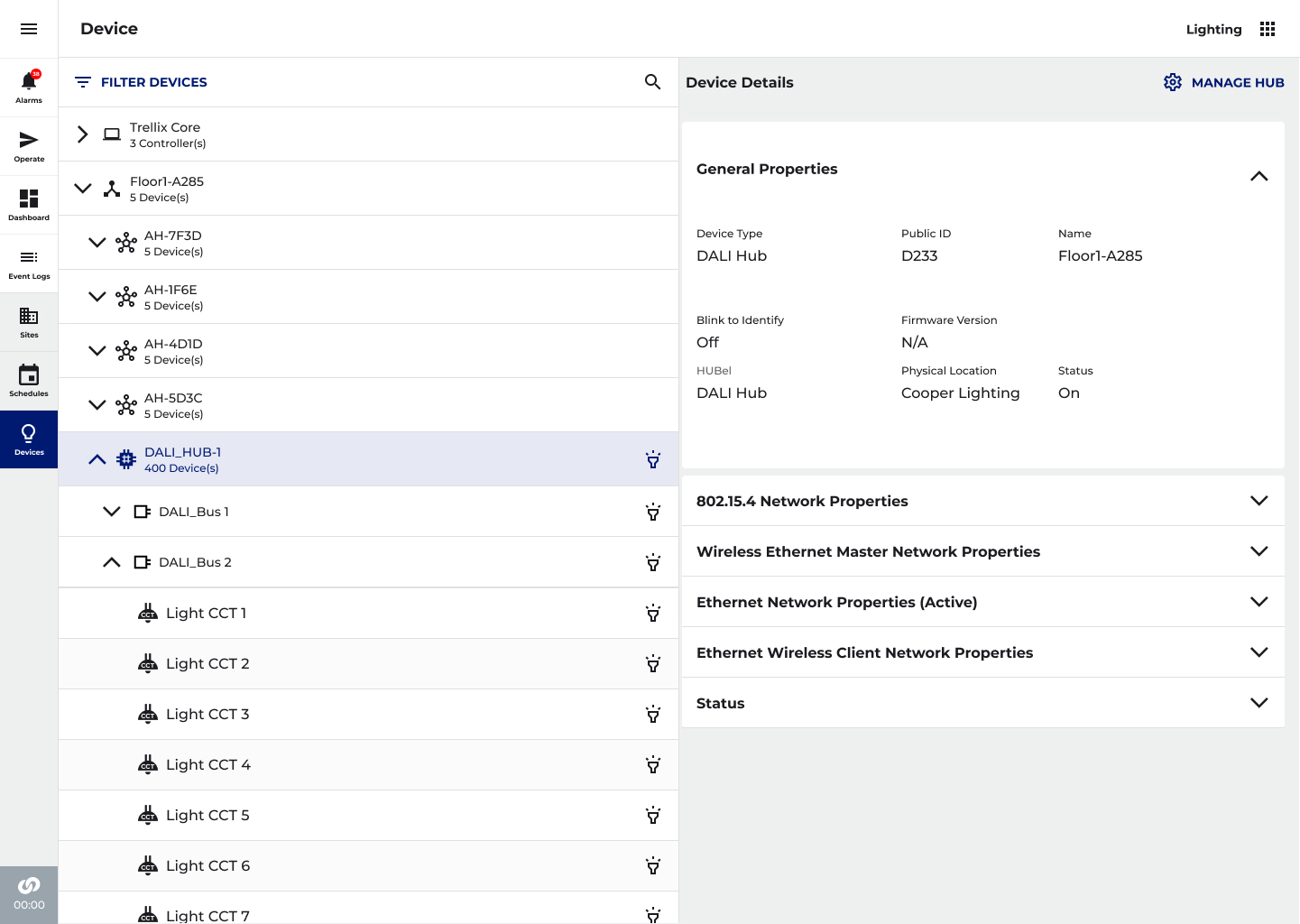
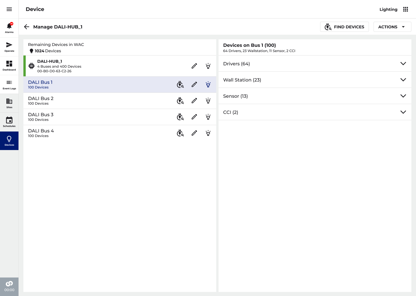
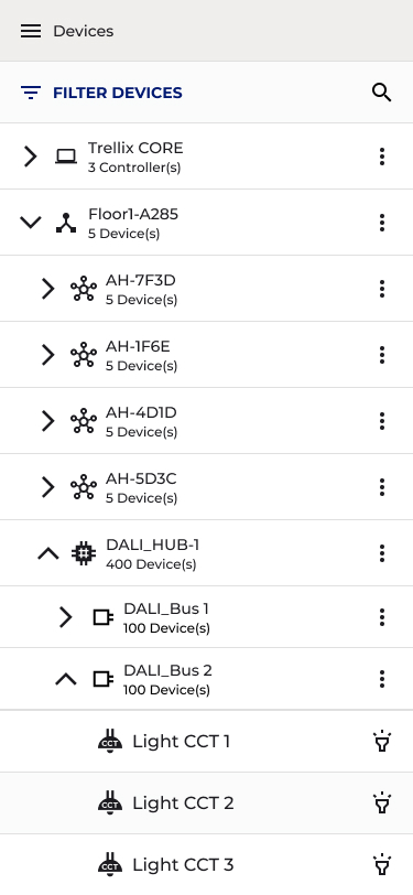
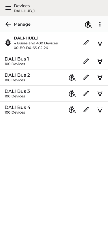
Manage Hub
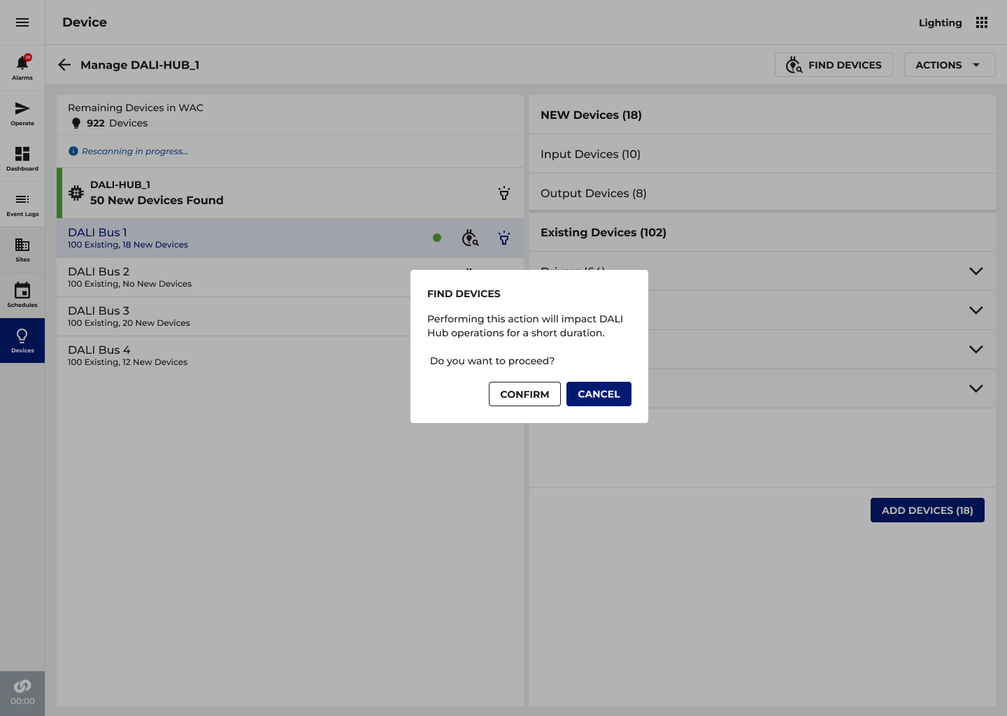
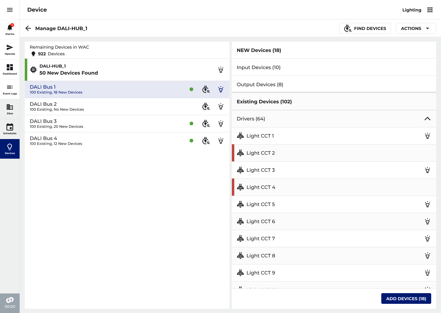
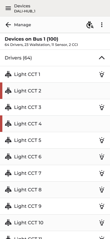
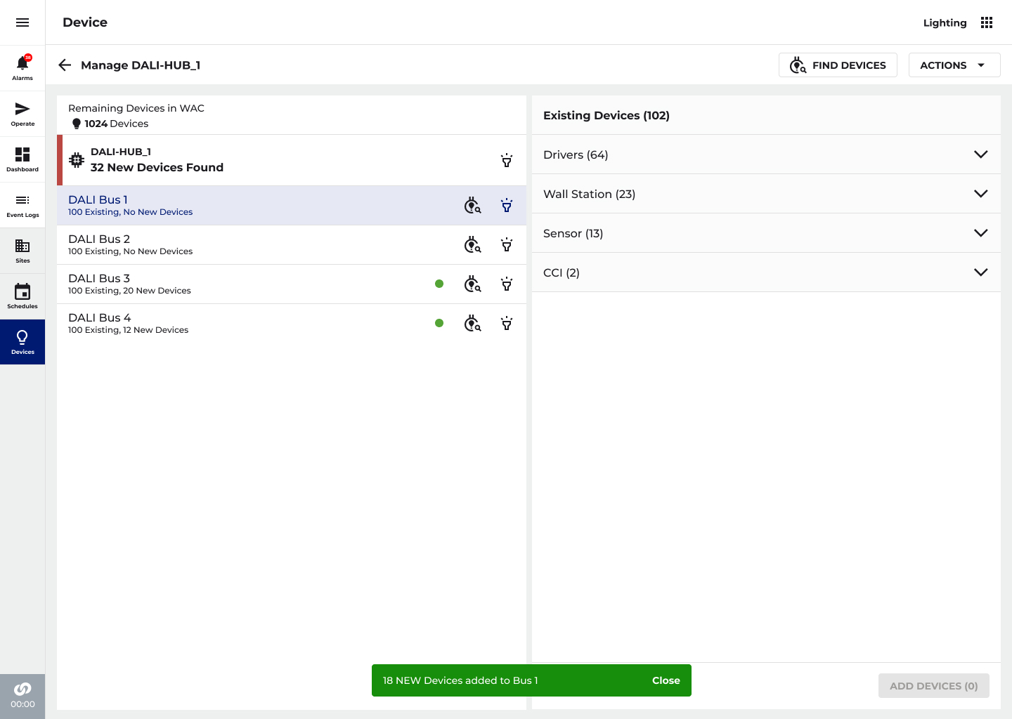
Left panel lists all buses under the hub with live device counts. Selecting a bus breaks down inventory by category, Drivers (64), Wall Stations (23), Sensors (13), CCIs (2). Persistent Remaining Devices in WAC counter provides installation-wide context.
Find Devices
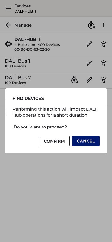
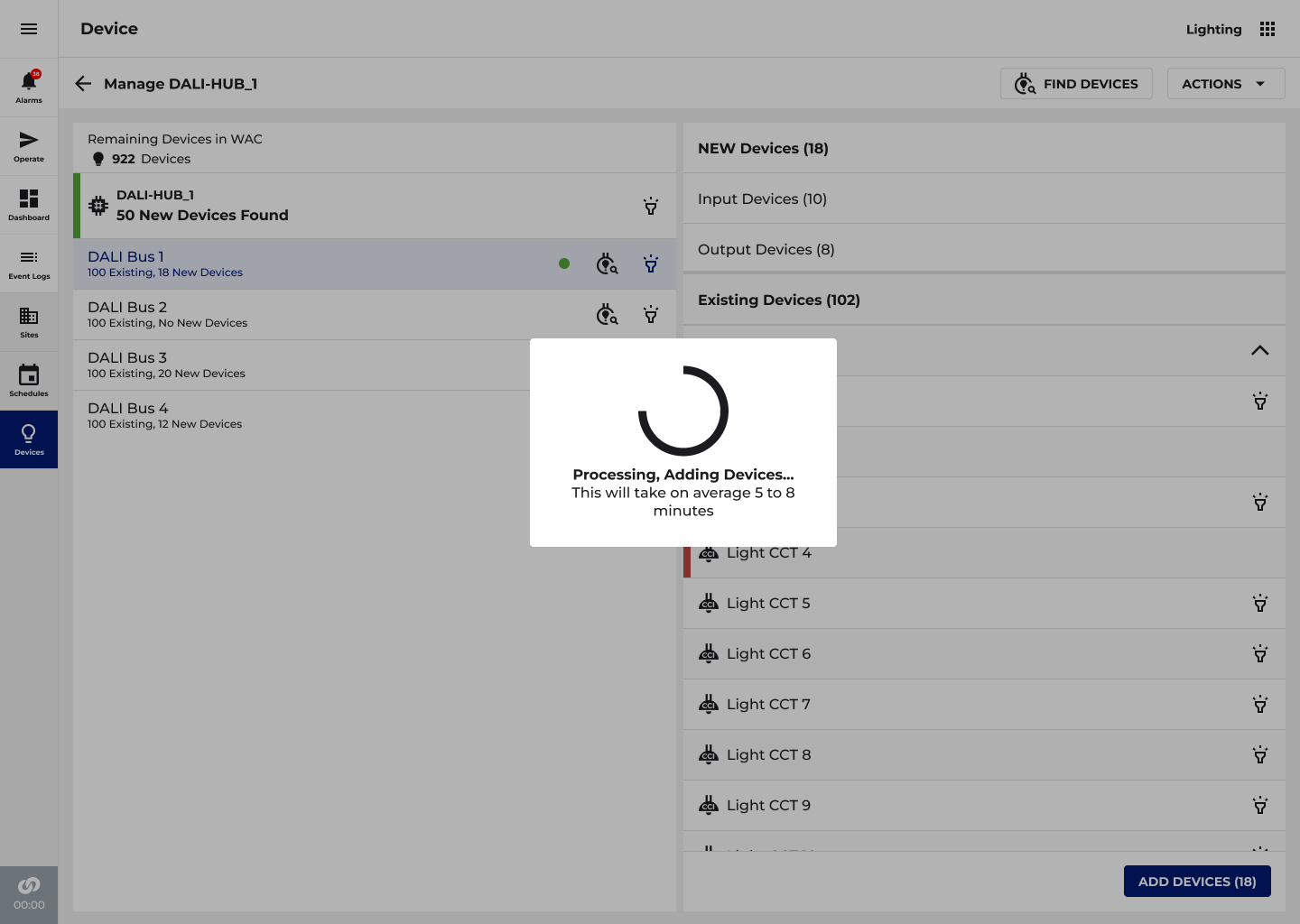
When devices are added to the physical installation post-commissioning, a common occurrence as hospital floors expand, the technician triggers Find Devices from the top bar. Because this scan temporarily impacts hub operations, a confirmation dialog protects against accidental triggering on a live system. Once confirmed, the system rescans all buses simultaneously. Buses with newly discovered devices are flagged with a green indicator and a count of new vs. existing devices, so the technician can quickly identify which buses require attention without scanning each one manually. The detail panel separates New Devices from Existing Devices, further organized by type (Input/Output), giving full clarity on exactly what has been found before anything is committed.
Add Devices
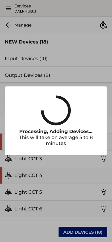
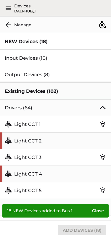
Buses with newly discovered devices are flagged with a green indicator and new device count. Detail panel separates New Devices from Existing Devices, organized by type. A single ADD DEVICES (n) action imports all. Processing modal sets expectations with a 5–8 minute estimate. Toast confirms: "18 NEW Devices added to Bus 1."
UX Design Decision
Separating new from existing devices before committing any changes was a deliberate safeguard at hospital scale, blindly importing an unexpected device count could cause significant downstream commissioning problems. The green bus indicators provide at-a-glance triage so technicians can prioritize which buses to address first. The processing modal with a time estimate was added specifically in response to feedback from commissioning teams who needed to plan around the 5–8 minute rescan window on a live hub.
07
DESIGN
Area Commissioning
💡 SOLVING THE DEVICE VOLUME PROBLEM IN SITES
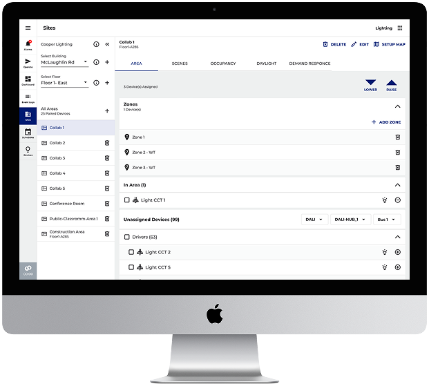
The existing WaveLinx Area screen was designed around a manageable number of wireless devices per controller. DALI-2 changed that equation entirely. A hospital floor running 6 or more hubs could surface thousands of fixtures, sensors, and wall stations simultaneously in the Unassigned Devices list, flooding the screen, crippling load times, and making it nearly impossible to locate and assign the right device.
The Solution — Filter-Before-Load
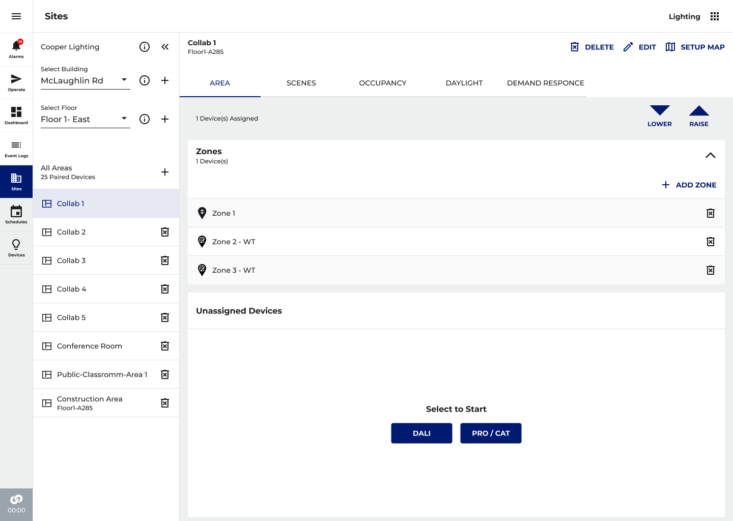
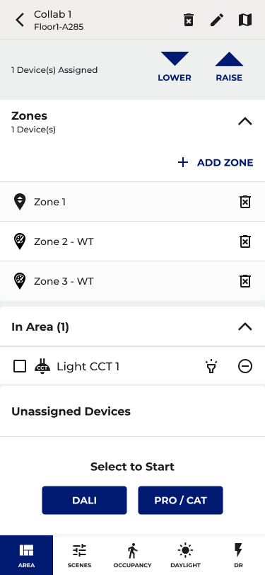
A system filter was introduced to the Unassigned Devices section: System (DALI or PRO/CAT), Hub, and Bus. Rather than loading all devices at once, the technician selects their scope, narrowing the list to a single bus and its 128 devices before any devices are rendered. A "Select Filter to Start" empty state enforces this intentionally, preventing accidental full-system loads that would time out or overwhelm the interface.
Filter-Before-Load Pattern
The "Select to Start" empty state with DALI and PRO/CAT buttons enforces intentional scoping. Once a system is selected, cascading Hub and Bus drop-down populate. Result: a readable, fast-loading device list scoped to exactly 128 devices per bus, not thousands.
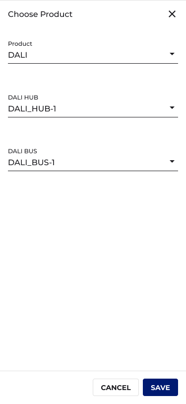
Scoped Device List
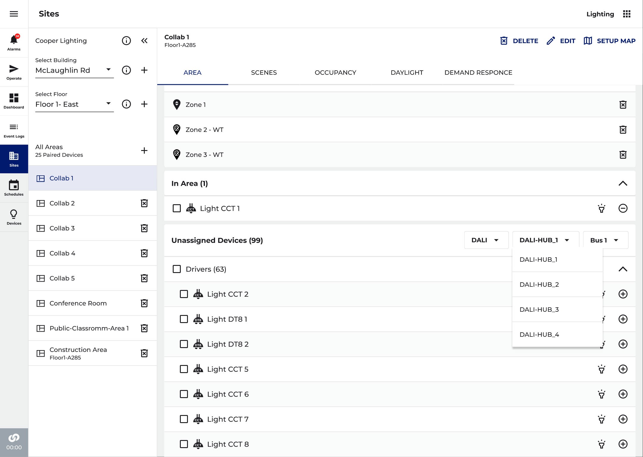
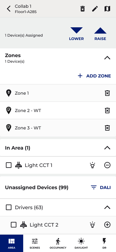
Once a Hub and Bus are selected, devices populate grouped by type, Drivers, Sensors, Wall Stations, CCIs. The DALI Hub dropdown lists all discovered hubs; the Bus dropdown cascades accordingly. Technicians always know exactly which physical segment they're working in.
UX Design Decision
The filter-before-load pattern was the central design decision, a deliberate shift from the existing "show everything" model to a scoped, intentional workflow. This wasn't just a performance fix; it reframes how technicians think about the work, encouraging a bus-by-bus approach that mirrors how DALI-2 is physically installed and wired. Working through one bus at a time reduces errors, keeps the screen readable, and maps directly to how the commissioning job is organized on the floor.
08
DESIGN
Floor Plan View
💡 REDESIGNING NAVIGATION FOR THOUSANDS OF DEVICES
The Operate floor plan view was built for a world where a floor might have 30–50 devices. DALI-2 changed that to 3,000+. The existing left-panel hierarchy would have required endless scrolling to navigate, triggered severe load time degradation, and made locating any specific device on a live hospital floor nearly impossible under time pressure. The entire navigation model needed to be reconsidered.
Removing the Hierarchy — Introducing Dropdown Navigation
The fixed left-panel hierarchy was replaced with a flat, contextual dropdown bar at the top of the screen: Building → Floor → Area → Zone → Device. Rather than loading the full device tree on entry, the user navigates by selecting from each dropdown in sequence, each choice scoping the next, loading only what's needed at that level. A technician can jump directly from Building to a specific Area without stepping through every intermediate level.
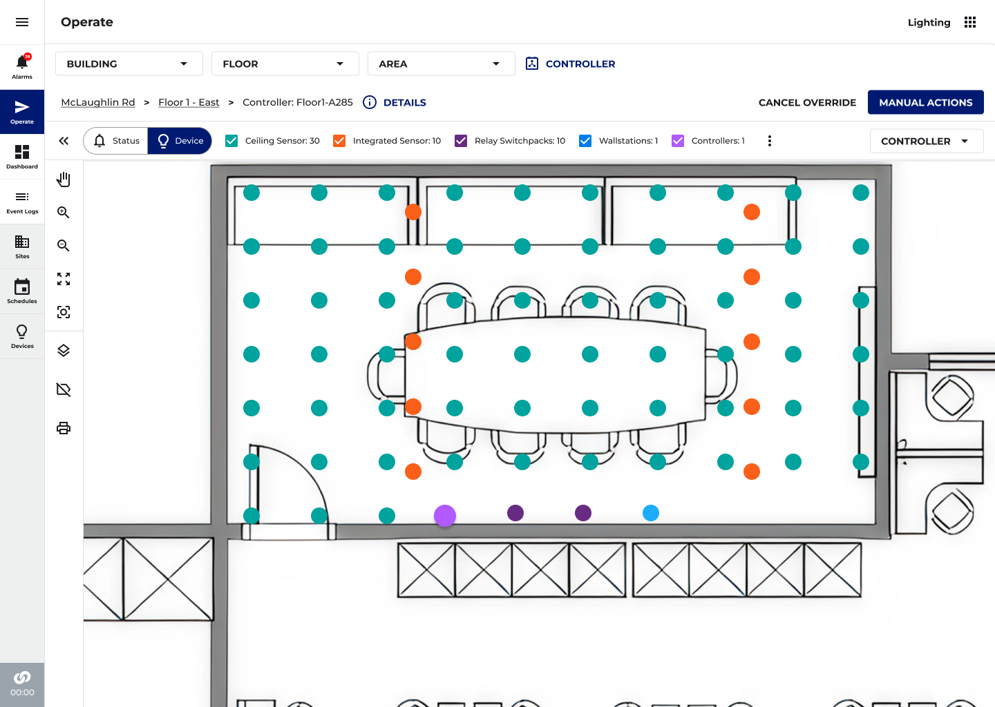
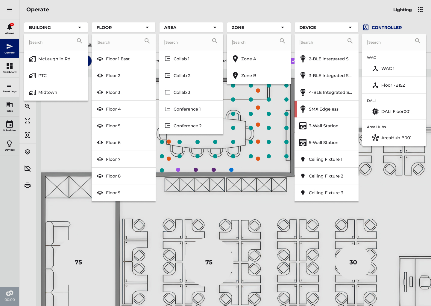
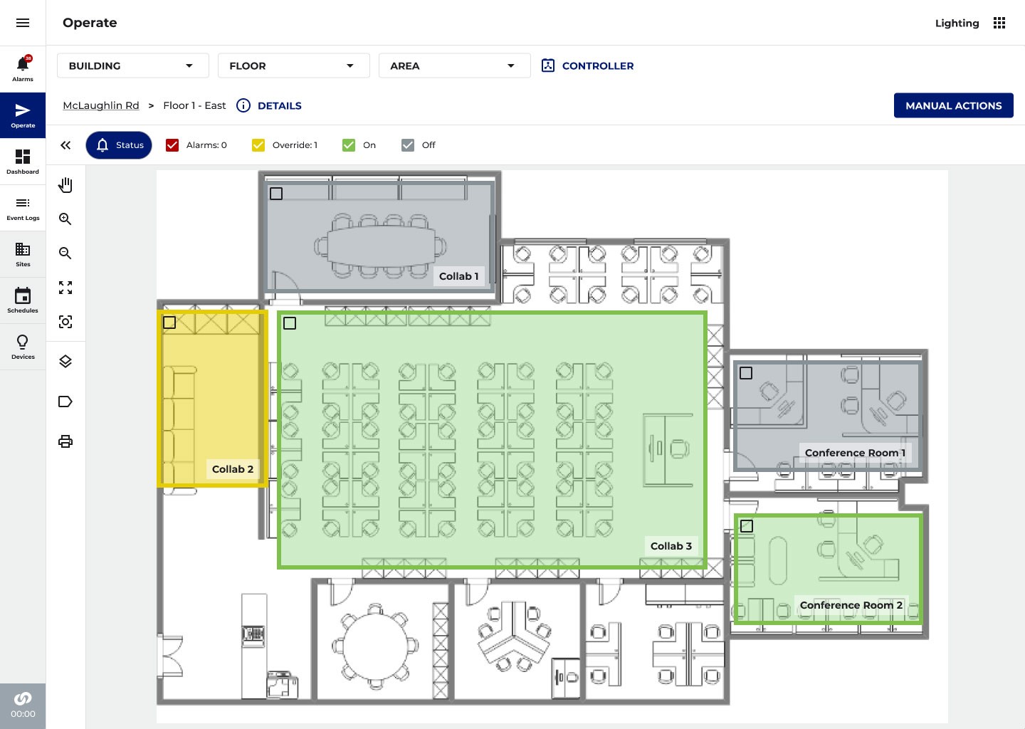
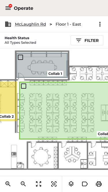
Dropdown Navigation / Breadcrumb / Legend
Building → Floor → Area → Zone → Device. Each dropdown surfaces the first five results immediately with search for longer lists. A breadcrumb trail below the dropdowns always shows current navigation context. Technicians can jump directly to any level without traversing every step.
Clustering for Spatial Clarity
At the floor level with hundreds of devices plotted, individual device markers would overlap into an unreadable mass. Clustering aggregates nearby devices into a single node based on zoom level, as the user zooms in, clusters break apart into individual devices, and zooming back out re-aggregates them. This keeps the floor plan readable and performant at every zoom level.
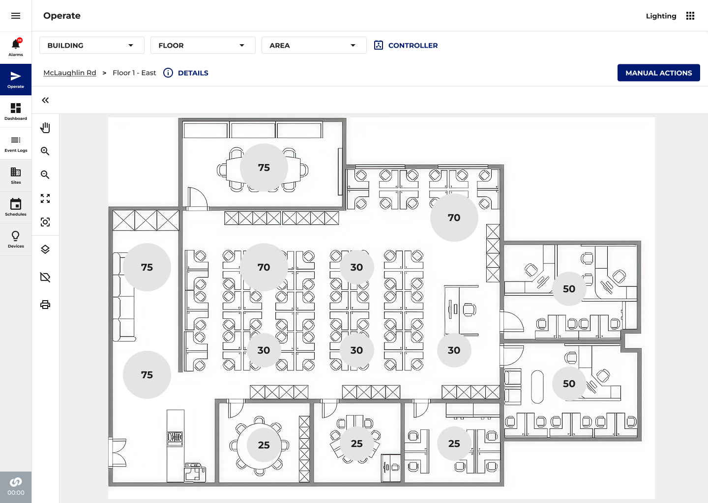
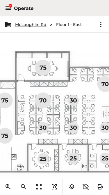
Device Clustering
Clustered view at floor level, numbers indicate device count per cluster. Gives technicians a spatial overview of device density before drilling in.
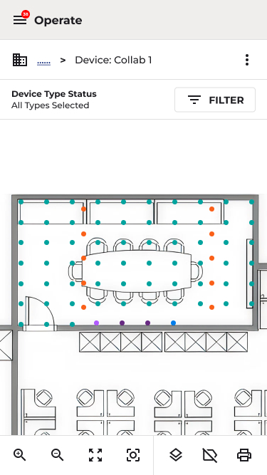
Device-Level View
Zooming in breaks clusters into individual device dots, color-coded by type. The same interaction model scales from a 50-device commercial install to a 3,000-device hospital floor without any change.
UX Design Decision
The shift from hierarchical tree to dropdown navigation was the most significant structural change in the entire DALI-2 project. It reframes the Operate screen from a device browser to a spatial tool, the floor plan becomes the primary interface, and the navigation bar becomes a scoping mechanism rather than a tree to traverse. Combined with clustering and type filtering, the result is a floor plan view that scales from a 50-device commercial install to a 3,000-device hospital floor without any change in the interaction model.
09
CLEAR REFLECTION
Iteration in Ambiguity
This project had a moving floor. Hardware prototypes arrived on a rolling basis. Third-party device availability was uncertain throughout. Rapid prototypes were used to pressure-test concepts quickly, weekly reviews with the full stakeholder group to iterate in lockstep with engineering decisions.
PhaseVersion 1 - Version 2 Pivot
ChallengeEngineering raised the blocking scan was unacceptable at scale. A UX presentation to Dev exposed the structural wait time issue. Version 1 spec had a 10-minute blocking import timeout.
Design ResponseInitiated Version 2 architecture. Reframed from "scan then configure" to "add Hub and configure while scan runs in background." Final timeout: 27.5 minutes, non-blocking.
PhaseManage Hub 3-Step
ChallengeInitial Manage Hub flow was an undifferentiated list. Field services and engineering flagged it as unclear for rescan and new device addition workflows.
Design ResponseDefined 3-step Manage Hub: (1) Rescan and find new devices, (2) Show device types and identify, (3) Add Devices with confirmation states and cancel at each step.
PhaseDevice Volume / Floor plan
ChallengeExisting floor plan hierarchy would have triggered severe load time degradation at DALI-2 scale. A broader stress-test audit was needed across the full application, not just the DALI feature set.
Design ResponseConducted a system-wide UX stress-test audit. Introduced dropdown navigation, clustering, and filter-before- load patterns to handle 3,000+ devices.
PhaseDT8 Dual Channel Zone Auto-Select
ChallengeDT8 drivers in areas with one White Tuning zone should auto- select. With multiple White Tuning zones, a 2-channel selection model was needed. Engineering confirmation required before UX could specify.
Design ResponseDefined the auto-select rule and multi- zone pattern mirroring the 2-channel PRO Node model
PhaseDevice Naming & Icons
ChallengeMultiple device types (DT6, DT8, DAC, Field Relay, CCI) in the same lists required consistent naming, iconography, and taxonomy before QA could write testable criteria.
Design ResponseCustom icon system designed with two-wire bus motif. Full naming convention defined across all device types. DALI 1 and DALI 2 DT6 confirmed to show identically in UI.
10
UX REVIEW
Outcomes
QA / UIQA
All scenarios PASS
200+ Devices
All device types validated by QA test site across 4 buses
0 → 1
Net-new product category, largest DALI-2 installation in North America
→
Hub-first non-blocking commissioning across Mobile App
→
Custom DALI-2 icon system, two-wire bus motif across all device types, SVG/Fontello validated
→
DALI-2 certified DT8 Dual Channel (CCT, white) LED driver support with auto-addressing
→
Identify at Hub, Bus, and Device level from Lobby, enabling physical-to-logical verification during installation
→
Filter-before-load area commissioning, scoped to single bus (128 devices) for performance and clarity at hospital
scale
→
Dropdown navigation + device clustering for floorplan view scales from 50 to 3,000+ devices with no model change
→
Mixed-protocol area support: DALI, CAT wired, and WaveLinx Wireless devices in the same zone
QA Validation
12 / 12
Test scenarios passed at QA regression bench
2 - 2.5s
CTQ: 0→100% light transition across all device types
Design System Leverage
Commissioning patterns from DALI, non-blocking scan, two-banner progress model, filter-before-load, dropdown navigation, device vs. endpoint display logic are now the reference architecture for future IoT subsystem integrations in WaveLinx, documented in the CLS Design System for reuse.
11
MY IMPACT
Why This Work Required My Background?
The WaveLinx DALI project is not a case study about making a hard UI easier to use. It's about designing a product that didn't exist, for a protocol that couldn't be changed, in an environment where hardware, firmware, and UX were all being built simultaneously, and where a wrong interaction architecture would have shipped inside a certified, hospital-grade IoT product deployed at the largest DALI-2 installation in North America.The V1-to-V2 pivot required recognizing that a 10-minute blocking import wasn't a UI problem to solve with better loading states, it was an architectural mismatch between the commissioning mental model and the DALI protocol's actual timing characteristics. The engineering answer was to increase the timeout to 27.5 minutes. The UX answer was to make the entire wait invisible by redesigning around it. Getting there required deep enough protocol knowledge to know what was and wasn't changeable at the firmware level.
The hardware bandwidth limitations, device naming, the dual channel/dual-zone abstraction, the floor plan hierarchy replacement, none of these were UX decisions made in isolation. They required navigating engineering constraints, product commitments, QA dependencies, and hardware availability simultaneously. My experience across connected lighting, enterprise SaaS, and hardware-adjacent environments gave me the credibility and domain fluency to lead these decisions rather than react to them.
Peter Gilgan Mississauga Hospital · First DALI-2 system of this scale in North America
WaveLinx DALI-2
Designing an industry-first commissioning experience for a protocol-constrained commercial IoT product from zero to shipped, across hardware, firmware, and field reality simultaneously.
ENTERPRISE IOT
HEALTHCARE
INDUSTRY FIRST
FIRST RELEASE COMPLETE

ROLE
Lead Product Designer
COMPANY
Cooper Lighting Solutions (Signify)
PLATFORM
Mobile, Web
SCOPE
Research → Delivery
TEAM SIZE
15 Cross-functional
DESIGNED
2024-2026 - Figma
VISIT WEBSITE
Key Outcome ↑
Delivered a design solution that extended WaveLinx's commissioning and device management workflows to support DALI-2 at enterprise scale for one of the most complex hospital lighting deployments in North America. The non-blocking V2 architecture allowed contractors to configure areas while device import ran in parallel.
10,000+
Devices
24
Buses per Floor
6
DALI Hubs per Panel
3,072
Devices per Panel
128
Fixtures per Bus
1,000 ft
Max Bus Length
4,000 - 10,000
Devices per Hospital Floor
01
THE PROBLEM
What am I working with?
Cooper Lighting Solutions had built its commercial and healthcare lighting business on two legacy platforms, Fifth Light and iLight. Both were being discontinued. The WaveLinx DALI system was the designated replacement: a new, DALI-2-certified IoT platform extending WaveLinx Pro into large commercial buildings and hospitals. The first deployment: The Peter Gilgan Mississauga Hospital, the largest DALI-2 installation in North America.
There was no existing product to iterate on. This is a design inside a highly constrained hardware system. The DALI-2 protocol defines tight rules about how devices communicate on a bus, what operations must happen in sequence, and how long those operations take. The protocol cannot be changed. The UX had to work within it.
4,000+
Minimum devices on a typical hospitaldeployment, up to 10,000+ at full scale
40 Buses
Up to 20 DALI Hubs x 4 buses each per WAC Controller
128 Max
Devices per bus, 64 output control gear + 64 input control devices
The Core UX Problem: Time
DALI's bus architecture has an inherent limitation: the protocol is slow. The V1 design model made it worse adding a Hub locked the UI with a blocking loader reading "Processing! This may take a while... Adding Dali Hub and Devices to WAC" that persisted until import completed. That import window started at 10 minutes. Engineering later increased it to 27.5 minutes per Hub to accommodate 250 physical DALI devices. Multiply that across 10 Hubs per WAC, and the scale of the blocking problem becomes concrete.
V1 Commissioning Problem
Discovery triggered an immediate full scan across all 4 buses. Adding a Hub locked the UI with a blocking loader, no navigation, no area creation, no configuration work possible until import completed. On large deployments this meant contractors sat idle during a protocol-imposed wait that could stretch past 10 minutes per Hub. No progress visibility, no fallback, no parallel work.
Business Stakes
This was the system replacing Fifth Light and iLight. Channel partners, integrators, and facilities teams at hospitals were evaluating whether WaveLinx DALI could credibly take over those workflows. Commissioning experience was a make-or-break differentiator, not a polish concern. A blocking experience at hospital scale was not acceptable.
02
MY ROLE AND SCOPE
Taking the Lead
I was the UX owner on DALI-2, the primary design story for the entire WaveLinx DALI commissioning system. I led UX strategy and design from discovery through handoff, collaborating cross-functionally with Engineering, Architecture, Product Management, Firmware, and Development. Milestone UX presentations were delivered to groups of 25+ stakeholders for feedback and alignment across the full initiative.
What I Owned
End-to-end commissioning UX across Hub Discovery, Lobby, Manage Hub, Area integration, and Floorplan view · V1 and V2 flow architecture · Custom iconography system (Adobe Illustrator → SVG/Fontello) · DALI-2 Hub hardware label design (press-ready) · Cross-functional design reviews · CLS Design System contributions in Figma · Launch followup
Direct team: Engineering Managers (2), ePO Engineering Product Owners (2), Product Managers (2), Architecture (1), Developers (5). I worked directly with the firmware engineer owning DALI bus scanning logic, translating protocol constraints into interaction affordances that felt coherent to end users.
Key Constraint
The DALI bus scan is slow by protocol design. Addressing 128 devices per bus and fetching device parameters takes real time. This was not a solvable engineering problem, the protocol ceiling is physical. The UX had to absorb the constraint and design around it, not through it.
03
SCOPING
Discovery, Research, Icons & System Design
Research and domain learning ran simultaneously with early design work, hardware prototypes and firmware builds were still in progress. My approach was to use the engineering team as a primary research source while the physical system was being built, supplemented by field context from channel partners and competitive teardown of existing DALI commissioning tools.
→
Deep protocol sessions with the firmware engineer, understanding what DALI-2 auto-addressing does, in sequence, and why it takes the time it takes
→
Review initiative documentation, mapping system architecture, device type hierarchy (DT6, DT8, Field Relay, CCI), and WAC capacity model
→
Legacy system teardown, evaluating Fifth Light and iLight commissioning to understand what behaviours installers expected to carry forward
→
Competitive analysis of 3 DALI commissioning platforms deployed in hospitals and commercial buildings
→
Early discovery workshops to surface bandwidth bottlenecks and technical constraints before any design work began stress-test audit of the full application, not just the DALI feature set
Research Approach
Discovery & Stakeholder AlignmentWith a project of this technical complexity, design-led research required bridging the gap between UX thinking and deep infrastructure knowledge. Work began with structured discovery sessions across five stakeholder groups before any design work started.
- Engineering & Firmware
Identified DALI bus bandwidth constraints, hub discovery latency, and the maximum polling frequency the system could support without degrading live commissioning
- Developers
Surfaced front-end rendering constraints, specifically, that loading 3,000+ devices into the existing device tree would time out and degrade the entire application
- Architecture & Product Management
Defined the hospital deployment context, commissioning workflow sequence, and regulatory requirements for wired-only environments
- Field Commissioning Teams
Described how technicians work on hospital floors: cross-referencing physical floor plans with MAC address lists, working bus-by-bus, and needing instant device identification under time pressure
- Hospital Facilities Teams
Articulated post-commissioning needs: adding devices during construction phase expansions, rebooting hubs without disrupting live floors, and identifying device faults quickly
User Input
I've been doing DALI for 12 years. I know what order things need to happen. But your app doesn't so I have to fight it.Master electrician, field context research participant
Key Research Insight
The single most important finding from discovery was that the existing WaveLinx architecture assumed a world of 30–50 devices per controller. Every piece of UI, device trees, area screens, the Operate floorplan, had been designed at that scale. DALI-2 didn’t just add a feature; it required re-examining how the entire application handled volume.
Custom Iconography System
The DALI 2-wire bus became the visual foundation of the icon system. The two-wire connection, the defining physical characteristic of every DALI device is embedded consistently across the icon set as a shared visual motif, allowing users to immediately recognize DALI devices as a category while differentiating by type at a glance. All icons were custom-designed in Adobe Illustrator, optimized for clarity at small sizes, exported in SVG format, and validated for rendering consistency via Fontello.

Fixture Dimmable

Light Fixture DT8

Light Fixture DT6 Single Channel

Light Fixture DT6 Dual Channel

Light Fixture CCT

DALI Hub

DALI Hub Bus

Dual Tech Sensor


PIR Sensor

Wall Station

Contact Closure Input

RSP DAC CCT

RSP DAC Dimmable

Relay on/off

Find Devices
DALI-2 Icon System — Custom designed in Adobe Illustrator
The two-wire bus motif is embedded in every device icon as a shared visual language, bridging physical installation and software management. Exported as SVG, validated via Fontello for rendering consistency at all display sizes.
DALI-2 Label Design
A sticker will be added to the HUB hardware providing specifications, describing install/setup and technical assistance. Design was created in Adobe Illustrator and is press ready with die cut marks in PDF format.*Graphical place holders added for LED lights and button locations
Four Key Insights
Insight 1 — The wait time was a UX problem before it was a technical one
The DALI bus scan delay wasn't fixable at the firmware level for MVP. But V1 made it worse by blocking the entire UI. The opportunity wasn't to make scanning faster, it was to stop making the user wait for it. Design needed to decouple scan from configuration workflow entirely.
Insight 2 — Hub-first import was the right architecture
Early designs explored adding devices during Hub discovery. Research and engineering collaboration revealed this was wrong: the Hub is the unit of import; devices are a consequence. Hub-first simplified the mental model, reduced decisions at the most uncertain moment, and aligned with how MQTT pairing actually worked.
Insight 3 — DT8 (dual channel) drivers created an invisible complexity problem
DALI DT8 drivers (CCT, white) physically present as a single device but require two separate zone types, Dimmable and White Tunable. Users see one fixture on the wall, two objects in the app. This disconnect required specific UX abstraction to avoid commissioning errors.
Insight 4 — The device volume problem would break existing UI patterns
The existing Area screen was designed for manageable wireless device counts. A hospital floor running 6+ Hubs could surface thousands of fixtures, sensors, and wall stations simultaneously, flooding the screen and crippling load times. The entire navigation model needed reconsidering at scale.
Rapid Prototyping Process
Weekly cross-functional reviews were the primary feedback mechanism throughout the project. Each cycle followed the same structure
Week 1 - 2
Flows for each problem area shared with Engineering to validate technical feasibility
Week 3 - 4
Prototypes reviewed with Product Management and Architecture for workflow alignment
Week 5+
Flows reviewed weekly with full stakeholder group including Firmware and Development leads
This cadence compressed the feedback loop significantly and allowed design decisions to stay in lockstep with evolving engineering constraints, particularly as hub discovery latency numbers changed and affected what real-time feedback the UI could reliably provide.
04
PIVOT
The Version 1 → Version 2 Pivot
Midway through the project it became clear the V1 commissioning model was structurally broken for the wait time problem. The pivot from V1 to V2 was not a visual redesign, it was a fundamental change to the interaction architecture.
V1 Model — Abandoned
Discover Hubs AND Devices simultaneously. Adding a Hub blocks the UI with a loading screen, no navigation, no configuration possible. User waits through a 10-minute+ blocking import per Hub.
→
V2 Model — Shipped
Discover ONLY DALI Hubs. ADD TO WAC triggers Hub pairing AND background bus scan simultaneously. UI never blocks. Users immediately begin configuring Areas while device import runs in background.
The Reframe in One Sentence
We stopped designing for when scanning finishes and started designing for what users can do while its still running.
05
DESIGN
DALI Hub Discovery & Commissioning Flow
💡 DESIGNING FOR SPEED AND CONFIDENCE AT HOSPITAL SCALE
Commissioning a hospital-scale DALI-2 installation means a technician may be working through hundreds of hubs, buses, and thousands of devices, often cross-referencing physical floor plans with MAC addresses in real time. The discovery flow needed to be fast, forgiving, and transparent about what the system had found at every step.
Step 1 — Scan the Network
From the Device screen, the technician initiates a network scan. A modal overlay confirms the system is actively scanning the IP network. Once complete, all discovered DALI Hubs are presented, each identified by name, MAC address, and IP address, ready to be imported into the WAC.
Step 2 — Select & Add a Hub
Selecting a Hub reveals a two-step stepper. All 4 buses shown with live device counts (Input and Output separately). Persistent Remaining Devices counter tracks across the full installation.
Step 3 — Name the Hub and Buses
Step 2 of the stepper prompts renaming using a consistent naming convention tied to floor and location. Inline edit and delete controls keep the interface clean. FINISH returns to the hub list.
Success State
Import confirmed with hub name, checkmark, and remaining device count, so the technician can move confidently to the next hub. Green tick appears against the Hub name in the list, indicating WAC import is complete.
06
DESIGN
DALI Hub Management
💡 ONGOING DEVICE MANAGEMENT AT HOSPITAL SCALE
Initial commissioning is only the beginning. Hospitals expand, floors get reconfigured, and new devices get added to existing buses over time. The Manage Hub screen supports the full lifecycle of a DALI-2 installation, giving technicians a persistent, reliable way to monitor hub health, add new devices, and take corrective action without disrupting a live facility.
Manage Hub
Left panel lists all buses under the hub with live device counts. Selecting a bus breaks down inventory by category, Drivers (64), Wall Stations (23), Sensors (13), CCIs (2). Persistent Remaining Devices in WAC counter provides installation-wide context.
Find Devices
When devices are added to the physical installation post-commissioning, a common occurrence as hospital floors expand, the technician triggers Find Devices from the top bar. Because this scan temporarily impacts hub operations, a confirmation dialog protects against accidental triggering on a live system. Once confirmed, the system rescans all buses simultaneously. Buses with newly discovered devices are flagged with a green indicator and a count of new vs. existing devices, so the technician can quickly identify which buses require attention without scanning each one manually. The detail panel separates New Devices from Existing Devices, further organized by type (Input/Output), giving full clarity on exactly what has been found before anything is committed.
Add Devices
Buses with newly discovered devices are flagged with a green indicator and new device count. Detail panel separates New Devices from Existing Devices, organized by type. A single ADD DEVICES (n) action imports all. Processing modal sets expectations with a 5–8 minute estimate. Toast confirms: "18 NEW Devices added to Bus 1."
UX Design Decision
Separating new from existing devices before committing any changes was a deliberate safeguard at hospital scale, blindly importing an unexpected device count could cause significant downstream commissioning problems. The green bus indicators provide at-a-glance triage so technicians can prioritize which buses to address first. The processing modal with a time estimate was added specifically in response to feedback from commissioning teams who needed to plan around the 5–8 minute rescan window on a live hub.
07
DESIGN
Area Commissioning
💡 SOLVING THE DEVICE VOLUME PROBLEM IN SITES
The existing WaveLinx Area screen was designed around a manageable number of wireless devices per controller. DALI-2 changed that equation entirely. A hospital floor running 6 or more hubs could surface thousands of fixtures, sensors, and wall stations simultaneously in the Unassigned Devices list, flooding the screen, crippling load times, and making it nearly impossible to locate and assign the right device.
The Solution — Filter-Before-Load
A system filter was introduced to the Unassigned Devices section: System (DALI or PRO/CAT), Hub, and Bus. Rather than loading all devices at once, the technician selects their scope, narrowing the list to a single bus and its 128 devices before any devices are rendered. A "Select Filter to Start" empty state enforces this intentionally, preventing accidental full-system loads that would time out or overwhelm the interface.
Filter-Before-Load Pattern
The "Select to Start" empty state with DALI and PRO/CAT buttons enforces intentional scoping. Once a system is selected, cascading Hub and Bus drop-down populate. Result: a readable, fast-loading device list scoped to exactly 128 devices per bus, not thousands.
Scoped Device List
Once a Hub and Bus are selected, devices populate grouped by type, Drivers, Sensors, Wall Stations, CCIs. The DALI Hub dropdown lists all discovered hubs; the Bus dropdown cascades accordingly. Technicians always know exactly which physical segment they're working in.
UX Design Decision
The filter-before-load pattern was the central design decision, a deliberate shift from the existing "show everything" model to a scoped, intentional workflow. This wasn't just a performance fix; it reframes how technicians think about the work, encouraging a bus-by-bus approach that mirrors how DALI-2 is physically installed and wired. Working through one bus at a time reduces errors, keeps the screen readable, and maps directly to how the commissioning job is organized on the floor.
08
DESIGN
Floor Plan View
💡 REDESIGNING NAVIGATION FOR THOUSANDS OF DEVICES
The Operate floor plan view was built for a world where a floor might have 30–50 devices. DALI-2 changed that to 3,000+. The existing left-panel hierarchy would have required endless scrolling to navigate, triggered severe load time degradation, and made locating any specific device on a live hospital floor nearly impossible under time pressure. The entire navigation model needed to be reconsidered.
Removing the Hierarchy — Introducing Dropdown Navigation
The fixed left-panel hierarchy was replaced with a flat, contextual dropdown bar at the top of the screen: Building → Floor → Area → Zone → Device. Rather than loading the full device tree on entry, the user navigates by selecting from each dropdown in sequence, each choice scoping the next, loading only what's needed at that level. A technician can jump directly from Building to a specific Area without stepping through every intermediate level.
Dropdown Navigation / Breadcrumb / Legend
Building → Floor → Area → Zone → Device. Each dropdown surfaces the first five results immediately with search for longer lists. A breadcrumb trail below the dropdowns always shows current navigation context. Technicians can jump directly to any level without traversing every step.
Clustering for Spatial Clarity
At the floor level with hundreds of devices plotted, individual device markers would overlap into an unreadable mass. Clustering aggregates nearby devices into a single node based on zoom level, as the user zooms in, clusters break apart into individual devices, and zooming back out re-aggregates them. This keeps the floor plan readable and performant at every zoom level.
Device Clustering
Clustered view at floor level, numbers indicate device count per cluster. Gives technicians a spatial overview of device density before drilling in.
Device-Level View
Zooming in breaks clusters into individual device dots, color-coded by type. The same interaction model scales from a 50-device commercial install to a 3,000-device hospital floor without any change.
UX Design Decision
The shift from hierarchical tree to dropdown navigation was the most significant structural change in the entire DALI-2 project. It reframes the Operate screen from a device browser to a spatial tool, the floor plan becomes the primary interface, and the navigation bar becomes a scoping mechanism rather than a tree to traverse. Combined with clustering and type filtering, the result is a floor plan view that scales from a 50-device commercial install to a 3,000-device hospital floor without any change in the interaction model.
09
CLEAR REFLECTION
Iteration in Ambiguity
This project had a moving floor. Hardware prototypes arrived on a rolling basis. Third-party device availability was uncertain throughout. Rapid prototypes were used to pressure-test concepts quickly, weekly reviews with the full stakeholder group to iterate in lockstep with engineering decisions.
Phase
Challenge
Design Response
Version 1 - Version 2 Pivot
Engineering raised the blocking scan was unacceptable at scale. A UX presentation to Dev exposed the structural wait time issue. Version 1 spec had a 10-minute blocking import timeout.
Initiated Version 2 architecture. Reframed from "scan then configure" to "add Hub and configure while scan runs in background." Final timeout: 27.5 minutes, non-blocking.
Manage Hub 3-Step
Initial Manage Hub flow was an undifferentiated list. Field services and engineering flagged it as unclear for rescan and new device addition workflows.
Defined 3-step Manage Hub: (1) Rescan and find new devices, (2) Show device types and identify, (3) Add Devices with confirmation states and cancel at each step.
Device Volume / Floor plan
Existing floor plan hierarchy would have triggered severe load time degradation at DALI-2 scale. A broader stress-test audit was needed across the full application, not just the DALI feature set.
Conducted a system-wide UX stress-test audit. Introduced dropdown navigation, clustering, and filter-before- load patterns to handle 3,000+ devices.
DT8 Dual Channel Zone Auto-Select
DT8 drivers in areas with one White Tuning zone should auto- select. With multiple White Tuning zones, a 2-channel selection model was needed. Engineering confirmation required before UX could specify.
Defined the auto-select rule and multi- zone pattern mirroring the 2-channel PRO Node model
Device Naming & Icons
Multiple device types (DT6, DT8, DAC, Field Relay, CCI) in the same lists required consistent naming, iconography, and taxonomy before QA could write testable criteria.
Custom icon system designed with two-wire bus motif. Full naming convention defined across all device types. DALI 1 and DALI 2 DT6 confirmed to show identically in UI.
10
UX REVIEW
Outcomes
QA / UIQA
All scenarios PASS
200+ Devices
All device types validated by QA test site across 4 buses
0 → 1
Net-new product category, largest DALI-2 installation in North America
→
Hub-first non-blocking commissioning across Mobile App
→
Custom DALI-2 icon system, two-wire bus motif across all device types, SVG/Fontello validated
→
DALI-2 certified DT8 Dual Channel (CCT, white) LED driver support with auto-addressing
→
Identify at Hub, Bus, and Device level from Lobby, enabling physical-to-logical verification during installation
→
Filter-before-load area commissioning, scoped to single bus (128 devices) for performance and clarity at hospital
scale
→
Dropdown navigation + device clustering for floorplan view scales from 50 to 3,000+ devices with no model change
→
Mixed-protocol area support: DALI, CAT wired, and WaveLinx Wireless devices in the same zone
QA Validation
12 / 12
Test scenarios passed at QA regression bench
2 - 2.5s
CTQ: 0→100% light transition across all device types
Design System Leverage
Commissioning patterns from DALI, non-blocking scan, two-banner progress model, filter-before-load, dropdown navigation, device vs. endpoint display logic are now the reference architecture for future IoT subsystem integrations in WaveLinx, documented in the CLS Design System for reuse.
11
MY IMPACT
Why This Work Required My Background?
The WaveLinx DALI project is not a case study about making a hard UI easier to use. It's about designing a product that didn't exist, for a protocol that couldn't be changed, in an environment where hardware, firmware, and UX were all being built simultaneously, and where a wrong interaction architecture would have shipped inside a certified, hospital-grade IoT product deployed at the largest DALI-2 installation in North America.The V1-to-V2 pivot required recognizing that a 10-minute blocking import wasn't a UI problem to solve with better loading states, it was an architectural mismatch between the commissioning mental model and the DALI protocol's actual timing characteristics. The engineering answer was to increase the timeout to 27.5 minutes. The UX answer was to make the entire wait invisible by redesigning around it. Getting there required deep enough protocol knowledge to know what was and wasn't changeable at the firmware level.
The hardware bandwidth limitations, device naming, the dual channel/dual-zone abstraction, the floor plan hierarchy replacement, none of these were UX decisions made in isolation. They required navigating engineering constraints, product commitments, QA dependencies, and hardware availability simultaneously. My experience across connected lighting, enterprise SaaS, and hardware-adjacent environments gave me the credibility and domain fluency to lead these decisions rather than react to them.
Peter Gilgan Mississauga Hospital · First DALI-2 system of this scale in North America
WaveLinx DALI-2
Designing an industry-first commissioning experience for a protocol-constrained commercial IoT product from zero to shipped, across hardware, firmware, and field reality simultaneously.
ENTERPRISE IOT
HEALTHCARE
INDUSTRY FIRST
FIRST RELEASE COMPLETE

ROLE
Lead Product Designer
COMPANY
Cooper Lighting Solutions (Signify)
PLATFORM
Mobile, Web
SCOPE
Research → Delivery
TEAM SIZE
15 Cross-functional
DESIGNED
2024-2026 - Figma
VISIT WEBSITE
Key Outcome ↑
Delivered a design solution that extended WaveLinx's commissioning and device management workflows to support DALI-2 at enterprise scale for one of the most complex hospital lighting deployments in North America. The non-blocking V2 architecture allowed contractors to configure areas while device import ran in parallel.
10,000+
Devices
24
Buses per Floor
6
DALI Hubs per Panel
3,072
Devices per Panel
128
Fixtures per Bus
1,000 ft
Max Bus Length
4,000 - 10,000
Devices per Hospital Floor
01
THE PROBLEM
What am I working with?
Cooper Lighting Solutions had built its commercial and healthcare lighting business on two legacy platforms, Fifth Light and iLight. Both were being discontinued. The WaveLinx DALI system was the designated replacement: a new, DALI-2-certified IoT platform extending WaveLinx Pro into large commercial buildings and hospitals. The first deployment: The Peter Gilgan Mississauga Hospital, the largest DALI-2 installation in North America.
There was no existing product to iterate on. This is a design inside a highly constrained hardware system. The DALI-2 protocol defines tight rules about how devices communicate on a bus, what operations must happen in sequence, and how long those operations take. The protocol cannot be changed. The UX had to work within it.
4,000+
Minimum devices on a typical hospitaldeployment, up to 10,000+ at full scale
40 Buses
Up to 20 DALI Hubs x 4 buses each per WAC Controller
128 Max
Devices per bus, 64 output control gear + 64 input control devices
The Core UX Problem: Time
DALI's bus architecture has an inherent limitation: the protocol is slow. The V1 design model made it worse adding a Hub locked the UI with a blocking loader reading "Processing! This may take a while... Adding Dali Hub and Devices to WAC" that persisted until import completed. That import window started at 10 minutes. Engineering later increased it to 27.5 minutes per Hub to accommodate 250 physical DALI devices. Multiply that across 10 Hubs per WAC, and the scale of the blocking problem becomes concrete.
V1 Commissioning Problem
Discovery triggered an immediate full scan across all 4 buses. Adding a Hub locked the UI with a blocking loader, no navigation, no area creation, no configuration work possible until import completed. On large deployments this meant contractors sat idle during a protocol-imposed wait that could stretch past 10 minutes per Hub. No progress visibility, no fallback, no parallel work.
Business Stakes
This was the system replacing Fifth Light and iLight. Channel partners, integrators, and facilities teams at hospitals were evaluating whether WaveLinx DALI could credibly take over those workflows. Commissioning experience was a make-or-break differentiator, not a polish concern. A blocking experience at hospital scale was not acceptable.
02
MY ROLE AND SCOPE
Taking the Lead
I was the UX owner on DALI-2, the primary design story for the entire WaveLinx DALI commissioning system. I led UX strategy and design from discovery through handoff, collaborating cross-functionally with Engineering, Architecture, Product Management, Firmware, and Development. Milestone UX presentations were delivered to groups of 25+ stakeholders for feedback and alignment across the full initiative.
What I Owned
End-to-end commissioning UX across Hub Discovery, Lobby, Manage Hub, Area integration, and Floorplan view · V1 and V2 flow architecture · Custom iconography system (Adobe Illustrator → SVG/Fontello) · DALI-2 Hub hardware label design (press-ready) · Cross-functional design reviews · CLS Design System contributions in Figma · Launch followup
Direct team: Engineering Managers (2), ePO Engineering Product Owners (2), Product Managers (2), Architecture (1), Developers (5). I worked directly with the firmware engineer owning DALI bus scanning logic, translating protocol constraints into interaction affordances that felt coherent to end users.
Key Constraint
The DALI bus scan is slow by protocol design. Addressing 128 devices per bus and fetching device parameters takes real time. This was not a solvable engineering problem, the protocol ceiling is physical. The UX had to absorb the constraint and design around it, not through it.
03
SCOPING
Discovery, Research, Icons & System Design
Research and domain learning ran simultaneously with early design work, hardware prototypes and firmware builds were still in progress. My approach was to use the engineering team as a primary research source while the physical system was being built, supplemented by field context from channel partners and competitive teardown of existing DALI commissioning tools.
→
Deep protocol sessions with the firmware engineer, understanding what DALI-2 auto-addressing does, in sequence, and why it takes the time it takes
→
Review initiative documentation, mapping system architecture, device type hierarchy (DT6, DT8, Field Relay, CCI), and WAC capacity model
→
Legacy system teardown, evaluating Fifth Light and iLight commissioning to understand what behaviours installers expected to carry forward
→
Competitive analysis of 3 DALI commissioning platforms deployed in hospitals and commercial buildings
→
Early discovery workshops to surface bandwidth bottlenecks and technical constraints before any design work began stress-test audit of the full application, not just the DALI feature set
Research Approach
Discovery & Stakeholder AlignmentWith a project of this technical complexity, design-led research required bridging the gap between UX thinking and deep infrastructure knowledge. Work began with structured discovery sessions across five stakeholder groups before any design work started.
- Engineering & Firmware
Identified DALI bus bandwidth constraints, hub discovery latency, and the maximum polling frequency the system could support without degrading live commissioning
- Developers
Surfaced front-end rendering constraints, specifically, that loading 3,000+ devices into the existing device tree would time out and degrade the entire application
- Architecture & Product Management
Defined the hospital deployment context, commissioning workflow sequence, and regulatory requirements for wired-only environments
- Field Commissioning Teams
Described how technicians work on hospital floors: cross-referencing physical floor plans with MAC address lists, working bus-by-bus, and needing instant device identification under time pressure
- Hospital Facilities Teams
Articulated post-commissioning needs: adding devices during construction phase expansions, rebooting hubs without disrupting live floors, and identifying device faults quickly
User Input
I've been doing DALI for 12 years. I know what order things need to happen. But your app doesn't so I have to fight it.Master electrician, field context research participant
Key Research Insight
The single most important finding from discovery was that the existing WaveLinx architecture assumed a world of 30–50 devices per controller. Every piece of UI, device trees, area screens, the Operate floorplan, had been designed at that scale. DALI-2 didn’t just add a feature; it required re-examining how the entire application handled volume.
Custom Iconography System
The DALI 2-wire bus became the visual foundation of the icon system. The two-wire connection, the defining physical characteristic of every DALI device is embedded consistently across the icon set as a shared visual motif, allowing users to immediately recognize DALI devices as a category while differentiating by type at a glance. All icons were custom-designed in Adobe Illustrator, optimized for clarity at small sizes, exported in SVG format, and validated for rendering consistency via Fontello.
Fixture Dimmable
Light Fixture DT8
Light Fixture DT6 Single Channel
Light Fixture DT6 Dual Channel
Light Fixture CCT
DALI Hub
DALI Hub Bus
Dual Tech Sensor
PIR Sensor
Wall Station
Contact Closure Input
RSP DAC CCT
RSP DAC Dimmable
Relay on/off
Find Devices
DALI-2 Icon System — Custom designed in Adobe Illustrator
The two-wire bus motif is embedded in every device icon as a shared visual language, bridging physical installation and software management. Exported as SVG, validated via Fontello for rendering consistency at all display sizes.
DALI-2 Label Design
A sticker will be added to the HUB hardware providing specifications, describing install/setup and technical assistance. Design was created in Adobe Illustrator and is press ready with die cut marks in PDF format.*Graphical place holders added for LED lights and button locations
Four Key Insights
Insight 1 — The wait time was a UX problem before it was a technical one
The DALI bus scan delay wasn't fixable at the firmware level for MVP. But V1 made it worse by blocking the entire UI. The opportunity wasn't to make scanning faster, it was to stop making the user wait for it. Design needed to decouple scan from configuration workflow entirely.
Insight 2 — Hub-first import was the right architecture
Early designs explored adding devices during Hub discovery. Research and engineering collaboration revealed this was wrong: the Hub is the unit of import; devices are a consequence. Hub-first simplified the mental model, reduced decisions at the most uncertain moment, and aligned with how MQTT pairing actually worked.
Insight 3 — DT8 (dual channel) drivers created an invisible complexity problem
DALI DT8 drivers (CCT, white) physically present as a single device but require two separate zone types, Dimmable and White Tunable. Users see one fixture on the wall, two objects in the app. This disconnect required specific UX abstraction to avoid commissioning errors.
Insight 4 — The device volume problem would break existing UI patterns
The existing Area screen was designed for manageable wireless device counts. A hospital floor running 6+ Hubs could surface thousands of fixtures, sensors, and wall stations simultaneously, flooding the screen and crippling load times. The entire navigation model needed reconsidering at scale.
Rapid Prototyping Process
Weekly cross-functional reviews were the primary feedback mechanism throughout the project. Each cycle followed the same structure
Week 1 - 2
Flows for each problem area shared with Engineering to validate technical feasibility
Week 3 - 4
Prototypes reviewed with Product Management and Architecture for workflow alignment
Week 5+
Flows reviewed weekly with full stakeholder group including Firmware and Development leads
This cadence compressed the feedback loop significantly and allowed design decisions to stay in lockstep with evolving engineering constraints, particularly as hub discovery latency numbers changed and affected what real-time feedback the UI could reliably provide.
04
PIVOT
The Version 1 → Version 2 Pivot
Midway through the project it became clear the V1 commissioning model was structurally broken for the wait time problem. The pivot from V1 to V2 was not a visual redesign, it was a fundamental change to the interaction architecture.
V1 Model — Abandoned
Discover Hubs AND Devices simultaneously. Adding a Hub blocks the UI with a loading screen, no navigation, no configuration possible. User waits through a 10-minute+ blocking import per Hub.
→
V2 Model — Shipped
Discover ONLY DALI Hubs. ADD TO WAC triggers Hub pairing AND background bus scan simultaneously. UI never blocks. Users immediately begin configuring Areas while device import runs in background.
The Reframe in One Sentence
We stopped designing for when scanning finishes and started designing for what users can do while its still running.
05
DESIGN
DALI Hub Discovery & Commissioning Flow
💡 DESIGNING FOR SPEED AND CONFIDENCE AT HOSPITAL SCALE
Commissioning a hospital-scale DALI-2 installation means a technician may be working through hundreds of hubs, buses, and thousands of devices, often cross-referencing physical floor plans with MAC addresses in real time. The discovery flow needed to be fast, forgiving, and transparent about what the system had found at every step.
Step 1 — Scan the Network
From the Device screen, the technician initiates a network scan. A modal overlay confirms the system is actively scanning the IP network. Once complete, all discovered DALI Hubs are presented, each identified by name, MAC address, and IP address, ready to be imported into the WAC.
Step 2 — Select & Add a Hub
Selecting a Hub reveals a two-step stepper. All 4 buses shown with live device counts (Input and Output separately). Persistent Remaining Devices counter tracks across the full installation.
Step 3 — Name the Hub and Buses
Step 2 of the stepper prompts renaming using a consistent naming convention tied to floor and location. Inline edit and delete controls keep the interface clean. FINISH returns to the hub list.
Success State
Import confirmed with hub name, checkmark, and remaining device count, so the technician can move confidently to the next hub. Green tick appears against the Hub name in the list, indicating WAC import is complete.
06
DESIGN
DALI Hub Management
💡 ONGOING DEVICE MANAGEMENT AT HOSPITAL SCALE
Initial commissioning is only the beginning. Hospitals expand, floors get reconfigured, and new devices get added to existing buses over time. The Manage Hub screen supports the full lifecycle of a DALI-2 installation, giving technicians a persistent, reliable way to monitor hub health, add new devices, and take corrective action without disrupting a live facility.
Manage Hub
Left panel lists all buses under the hub with live device counts. Selecting a bus breaks down inventory by category, Drivers (64), Wall Stations (23), Sensors (13), CCIs (2). Persistent Remaining Devices in WAC counter provides installation-wide context.
Find Devices
When devices are added to the physical installation post-commissioning, a common occurrence as hospital floors expand, the technician triggers Find Devices from the top bar. Because this scan temporarily impacts hub operations, a confirmation dialog protects against accidental triggering on a live system. Once confirmed, the system rescans all buses simultaneously. Buses with newly discovered devices are flagged with a green indicator and a count of new vs. existing devices, so the technician can quickly identify which buses require attention without scanning each one manually. The detail panel separates New Devices from Existing Devices, further organized by type (Input/Output), giving full clarity on exactly what has been found before anything is committed.
Add Devices
Buses with newly discovered devices are flagged with a green indicator and new device count. Detail panel separates New Devices from Existing Devices, organized by type. A single ADD DEVICES (n) action imports all. Processing modal sets expectations with a 5–8 minute estimate. Toast confirms: "18 NEW Devices added to Bus 1."
UX Design Decision
Separating new from existing devices before committing any changes was a deliberate safeguard at hospital scale, blindly importing an unexpected device count could cause significant downstream commissioning problems. The green bus indicators provide at-a-glance triage so technicians can prioritize which buses to address first. The processing modal with a time estimate was added specifically in response to feedback from commissioning teams who needed to plan around the 5–8 minute rescan window on a live hub.
07
DESIGN
Area Commissioning
💡 SOLVING THE DEVICE VOLUME PROBLEM IN SITES
The existing WaveLinx Area screen was designed around a manageable number of wireless devices per controller. DALI-2 changed that equation entirely. A hospital floor running 6 or more hubs could surface thousands of fixtures, sensors, and wall stations simultaneously in the Unassigned Devices list, flooding the screen, crippling load times, and making it nearly impossible to locate and assign the right device.
The Solution — Filter-Before-Load
A system filter was introduced to the Unassigned Devices section: System (DALI or PRO/CAT), Hub, and Bus. Rather than loading all devices at once, the technician selects their scope, narrowing the list to a single bus and its 128 devices before any devices are rendered. A "Select Filter to Start" empty state enforces this intentionally, preventing accidental full-system loads that would time out or overwhelm the interface.
Filter-Before-Load Pattern
The "Select to Start" empty state with DALI and PRO/CAT buttons enforces intentional scoping. Once a system is selected, cascading Hub and Bus drop-down populate. Result: a readable, fast-loading device list scoped to exactly 128 devices per bus, not thousands.
Scoped Device List
Once a Hub and Bus are selected, devices populate grouped by type, Drivers, Sensors, Wall Stations, CCIs. The DALI Hub dropdown lists all discovered hubs; the Bus dropdown cascades accordingly. Technicians always know exactly which physical segment they're working in.
UX Design Decision
The filter-before-load pattern was the central design decision, a deliberate shift from the existing "show everything" model to a scoped, intentional workflow. This wasn't just a performance fix; it reframes how technicians think about the work, encouraging a bus-by-bus approach that mirrors how DALI-2 is physically installed and wired. Working through one bus at a time reduces errors, keeps the screen readable, and maps directly to how the commissioning job is organized on the floor.
08
DESIGN
Floor Plan View
💡 REDESIGNING NAVIGATION FOR THOUSANDS OF DEVICES
The Operate floor plan view was built for a world where a floor might have 30–50 devices. DALI-2 changed that to 3,000+. The existing left-panel hierarchy would have required endless scrolling to navigate, triggered severe load time degradation, and made locating any specific device on a live hospital floor nearly impossible under time pressure. The entire navigation model needed to be reconsidered.
Removing the Hierarchy — Introducing Dropdown Navigation
The fixed left-panel hierarchy was replaced with a flat, contextual dropdown bar at the top of the screen: Building → Floor → Area → Zone → Device. Rather than loading the full device tree on entry, the user navigates by selecting from each dropdown in sequence, each choice scoping the next, loading only what's needed at that level. A technician can jump directly from Building to a specific Area without stepping through every intermediate level.
Dropdown Navigation / Breadcrumb / Legend
Building → Floor → Area → Zone → Device. Each dropdown surfaces the first five results immediately with search for longer lists. A breadcrumb trail below the dropdowns always shows current navigation context. Technicians can jump directly to any level without traversing every step.
Clustering for Spatial Clarity
At the floor level with hundreds of devices plotted, individual device markers would overlap into an unreadable mass. Clustering aggregates nearby devices into a single node based on zoom level, as the user zooms in, clusters break apart into individual devices, and zooming back out re-aggregates them. This keeps the floor plan readable and performant at every zoom level.
Device Clustering
Clustered view at floor level, numbers indicate device count per cluster. Gives technicians a spatial overview of device density before drilling in.
Device-Level View
Zooming in breaks clusters into individual device dots, color-coded by type. The same interaction model scales from a 50-device commercial install to a 3,000-device hospital floor without any change.
UX Design Decision
The shift from hierarchical tree to dropdown navigation was the most significant structural change in the entire DALI-2 project. It reframes the Operate screen from a device browser to a spatial tool, the floor plan becomes the primary interface, and the navigation bar becomes a scoping mechanism rather than a tree to traverse. Combined with clustering and type filtering, the result is a floor plan view that scales from a 50-device commercial install to a 3,000-device hospital floor without any change in the interaction model.
09
CLEAR REFLECTION
Iteration in Ambiguity
This project had a moving floor. Hardware prototypes arrived on a rolling basis. Third-party device availability was uncertain throughout. Rapid prototypes were used to pressure-test concepts quickly, weekly reviews with the full stakeholder group to iterate in lockstep with engineering decisions.
Phase
Challenge
Design Response
Version 1 - Version 2 Pivot
Engineering raised the blocking scan was unacceptable at scale. A UX presentation to Dev exposed the structural wait time issue. Version 1 spec had a 10-minute blocking import timeout.
Initiated Version 2 architecture. Reframed from "scan then configure" to "add Hub and configure while scan runs in background." Final timeout: 27.5 minutes, non-blocking.
Manage Hub 3-Step
Initial Manage Hub flow was an undifferentiated list. Field services and engineering flagged it as unclear for rescan and new device addition workflows.
Defined 3-step Manage Hub: (1) Rescan and find new devices, (2) Show device types and identify, (3) Add Devices, with confirmation states and cancel at each step.
Device Volume / Floor plan
Existing floorplan hierarchy would have triggered severe load time degradation at DALI-2 scale. A broader stress-test audit was needed across the full application, not just the DALI feature set.
Conducted a system-wide UX stress-test audit. Introduced dropdown navigation, clustering, and filter-before- load patterns to handle 3,000+ devices.
DT8 Dual Channel Zone Auto-Select
DT8 drivers in areas with one White Tuning zone should auto- select. With multiple White Tuning zones, a 2-channel selection model was needed. Engineering confirmation required before UX could specify.
Defined the auto-select rule and multi- zone pattern mirroring the 2-channel PRO Node model
Device Naming & Icons
Multiple device types (DT6, DT8, DAC, Field Relay, CCI) in the same lists required consistent naming, iconography, and taxonomy before QA could write testable criteria.
Custom icon system designed with two-wire bus motif. Full naming convention defined across all device types. DALI 1 and DALI 2 DT6 confirmed to show identically in UI.
10
UX REVIEW
Outcomes
QA / UIQA
All scenarios PASS
200+ Devices
All device types validated by QA test site across 4 buses
0 → 1
Net-new product category, largest DALI-2 installation in North America
→
Hub-first non-blocking commissioning across Mobile App
→
Custom DALI-2 icon system, two-wire bus motif across all device types, SVG/Fontello validated
→
DALI-2 certified DT8 Dual Channel (CCT, white) LED driver support with auto-addressing
→
Identify at Hub, Bus, and Device level from Lobby, enabling physical-to-logical verification during installation
→
Filter-before-load area commissioning, scoped to single bus (128 devices) for performance and clarity at hospital
scale
→
Dropdown navigation + device clustering for floorplan view scales from 50 to 3,000+ devices with no model change
→
Mixed-protocol area support: DALI, CAT wired, and WaveLinx Wireless devices in the same zone
QA Validation
12 / 12
Test scenarios passed at QA regression bench
2 - 2.5s
CTQ: 0→100% light transition across all device types
Design System Leverage
Commissioning patterns from DALI, non-blocking scan, two-banner progress model, filter-before-load, dropdown navigation, device vs. endpoint display logic are now the reference architecture for future IoT subsystem integrations in WaveLinx, documented in the CLS Design System for reuse.
11
MY IMPACT
Why This Work Required My Background?
The WaveLinx DALI project is not a case study about making a hard UI easier to use. It's about designing a product that didn't exist, for a protocol that couldn't be changed, in an environment where hardware, firmware, and UX were all being built simultaneously, and where a wrong interaction architecture would have shipped inside a certified, hospital-grade IoT product deployed at the largest DALI-2 installation in North America.The V1-to-V2 pivot required recognizing that a 10-minute blocking import wasn't a UI problem to solve with better loading states, it was an architectural mismatch between the commissioning mental model and the DALI protocol's actual timing characteristics. The engineering answer was to increase the timeout to 27.5 minutes. The UX answer was to make the entire wait invisible by redesigning around it. Getting there required deep enough protocol knowledge to know what was and wasn't changeable at the firmware level.
The hardware bandwidth limitations, device naming, the dual channel/dual-zone abstraction, the floor plan hierarchy replacement, none of these were UX decisions made in isolation. They required navigating engineering constraints, product commitments, QA dependencies, and hardware availability simultaneously. My experience across connected lighting, enterprise SaaS, and hardware-adjacent environments gave me the credibility and domain fluency to lead these decisions rather than react to them.